Variable Refrigerant Flow systems have transformed commercial HVAC delivery — offering simultaneous heating and cooling, zone-level control, and energy efficiency improvements of 30–40% over conventional systems. But VRF's sophistication is a double-edged sword. With dozens of indoor units connected to outdoor condensing units through complex refrigerant piping networks and proprietary control protocols, maintenance complexity multiplies with every added zone. Traditional maintenance approaches — manual inspections, scheduled service visits, and reactive fault response — cannot keep pace with VRF system dynamics. Refrigerant imbalance, branch controller faults, indoor unit coil degradation, and inverter drive stress accumulate silently across the system while facility teams remain blind to early-warning signals. In 2026, digital management platforms combining IoT monitoring, AI diagnostics, and automated work order generation are giving facility managers complete visibility across every VRF component — detecting faults weeks before they cascade, optimizing refrigerant distribution in real time, and extending system service life by 8–12 years. iFactory's AI platform delivers this capability for your VRF portfolio. Book a free consultation to see digital VRF management in action for your building.
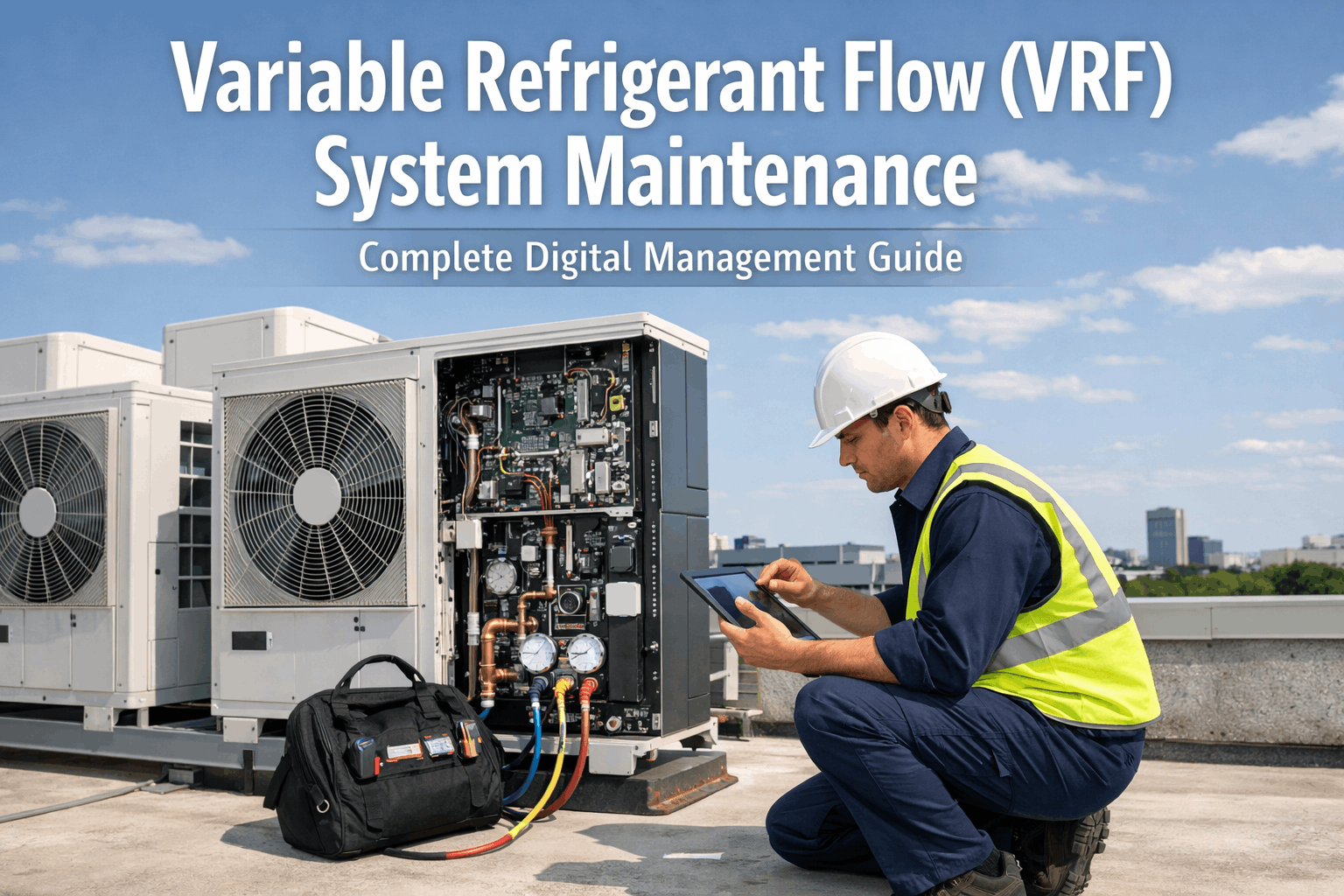
Variable Refrigerant Flow (VRF) System Maintenance
Complete Digital Management Guide
One outdoor unit. Dozens of indoor units. Miles of refrigerant piping. Hundreds of sensors. AI-powered digital management turns VRF complexity into a competitive advantage — delivering real-time fault detection, automated maintenance scheduling, and energy optimization across your entire system from a single platform.
Why VRF Systems Demand a Digital Approach
VRF systems generate more maintenance complexity per ton of cooling than any other commercial HVAC technology. Here are the four dimensions where conventional maintenance fails VRF operators.
Refrigerant Circuit Complexity
A single VRF system routes refrigerant through hundreds of feet of piping, multiple branch circuits, and dozens of electronic expansion valves — each of which can develop charge imbalance, restriction, or control drift independently. Manual inspection cannot detect these issues until system performance has already degraded significantly.
Multi-Unit Fault Cascade
In a VRF network, a fault in one indoor unit — a blocked coil, malfunctioning EXV, or failed thermistor — creates load shifts that stress the outdoor unit and adjacent circuits. What begins as a minor indoor unit issue becomes a compressor overload event if undetected. Cross-unit fault correlation is impossible without digital monitoring.
Proprietary Protocol Lock-In
VRF systems from Daikin, Mitsubishi, LG, Samsung, and Toshiba use proprietary communication protocols that prevent third-party BMS systems from accessing deep diagnostic data. Facility managers see only high-level on/off status — missing the rich operational data that resides inside the VRF controller network.
Multi-Mode Operational Complexity
VRF systems operate in heating, cooling, heat recovery, and defrost modes — with different performance benchmarks for each mode and transition. Evaluating whether a system parameter is anomalous requires knowing the current operating mode, outdoor conditions, and recent mode history. This contextual analysis is beyond manual capability at scale.
Six Pillars of Complete VRF Digital Management
A comprehensive digital management strategy addresses every layer of VRF operational complexity — from refrigerant circuit physics to occupant comfort delivery and energy cost optimization.
Real-Time Refrigerant Circuit Monitoring
Continuous tracking of suction and discharge pressures, subcooling, superheat, and EXV positions across every branch circuit. AI calculates refrigerant distribution balance across all indoor units simultaneously — detecting charge migration, restriction, and EXV drift with precision no manual inspection can match.
AI Fault Detection and Health Scoring
Each component in the VRF network — outdoor unit, branch controllers, and every indoor unit — receives a continuous 0–100 health score updated in real time. Machine learning models correlate cross-unit behavior patterns to identify developing faults 3–8 weeks before they trigger system alarms or cause comfort complaints.
Energy Performance Optimization
AI continuously benchmarks system COP against weather-normalized baselines — flagging degradation-driven energy waste in real time. Inverter drive efficiency tracking, compressor loading optimization, and heat recovery mode utilization analysis identify efficiency recovery opportunities worth $8,000–$35,000 annually per VRF system.
Automated Maintenance Scheduling
Condition-based maintenance replaces arbitrary service intervals. AI determines when each VRF component actually needs attention based on operating hours, fault score trends, and seasonal demand patterns. Work orders are automatically generated with component-specific tasks, required tools, and parts lists — dispatched directly to your CMMS platform.
Indoor Unit Coil and Filter Management
Dirty filters and fouled evaporator coils are the leading cause of indoor unit performance degradation — and the most overlooked in large VRF deployments. AI tracks airflow restriction trends across all indoor units, generating filter change and coil cleaning work orders precisely when needed rather than on fixed schedules that miss 40% of actual maintenance needs.
Multi-System Portfolio Management
Enterprise facility portfolios managing 5–500+ VRF systems across multiple buildings benefit from unified portfolio-level health dashboards, cross-site performance benchmarking, and centralized contractor management. AI identifies which systems need immediate attention, which are trending toward issues, and which are performing optimally — prioritizing maintenance resources across the portfolio.
VRF Fault Types AI Detects by Component
Each VRF component category has distinct failure patterns. AI models are pre-trained on fault signatures from all three layers of the VRF system.
Outdoor Condensing Unit
Current harmonic distortion, thermal cycling stress index, and DC bus voltage instability — tracked 5–9 weeks before drive failure.
Vibration frequency spectrum deviations correlated with discharge temperature anomalies — detected 4–7 weeks before failure.
Approach temperature trending against weather-normalized baselines — identifies cleaning need 4–8 weeks before COP degradation exceeds 10%.
Current draw trending and speed regulation deviation — catches motor bearing wear and capacitor degradation in early stages.
Defrost frequency, duration, and effectiveness scoring — detects sensor drift or control algorithm issues before they cause compressor stress.
Oil return rate estimation from refrigerant circuit data — flags oil migration risk before compressor lubrication is compromised.
Branch Circuit Controllers
Cross-branch superheat and subcooling variance analysis identifies circuits receiving insufficient or excess refrigerant — the primary cause of indoor unit performance variation.
Expansion valve instability — oscillating superheat and suction pressure — detected through pattern recognition before it causes compressor flooding or freeze events.
Proprietary protocol message error rate monitoring identifies wiring faults, connector corrosion, and controller board degradation before communication loss occurs.
Piping restriction identification through differential pressure analysis across branch circuits — detects contamination, ice formation, or piping damage early.
Indoor Fan Coil Units
Airflow resistance trending through fan motor load analysis — detects coil fouling and blocked filters 3–5 weeks before comfort complaints and energy waste become apparent.
Evaporator coil temperature pattern analysis identifies condensate drainage problems and biological growth before water damage events or air quality issues develop.
Motor current signature analysis detects fan blade damage or accumulated dirt causing vibration and aerodynamic imbalance — caught before motor bearing damage occurs.
Cross-validation of room temperature sensor readings against unit load behavior identifies sensor drift that causes control inaccuracy and comfort complaints.
Expansion valve response time degradation tracked through position-to-superheat correlation — identifies valve aging before it impairs capacity control accuracy.
Long-term cooling/heating capacity decline tracking against baseline — quantifies performance loss in tons per week to predict when unit replacement becomes more cost-effective than repair.
Digital VRF Management — Performance Data
| Metric | Conventional Approach | Digital AI Management | Outcome |
|---|---|---|---|
| Fault Detection Lead Time | At alarm or failure | 3–8 weeks ahead | Proactive |
| System Energy Efficiency | Baseline (degraded) | 18–28% improvement | +$12–35K/yr |
| Unplanned Downtime Events | 8–15 per year per system | 1–3 per year per system | 80% fewer |
| Emergency Repair Costs | $6,000–$40,000/event | $800–$3,000 planned | Up to 93% lower |
| Filter / Coil Service Accuracy | 40% over/under serviced | Condition-triggered only | Zero waste visits |
| System Service Life | 12–16 years typical | 20–28 years with AI care | +8–12 years |
| Indoor Comfort Complaints | Baseline | 65% reduction | Tenant satisfaction |
Estimated 5-year total cost benefit for a portfolio of 10 VRF systems through energy, repair, and life-extension savings
— Building Efficiency Institute, 2025Fault detection accuracy achieved after 90-day AI calibration on VRF-specific operational data and system architecture
— iFactory AI BenchmarkWant a custom ROI projection for your VRF fleet?
Get Free ROI Estimate ↗VRF Brands and System Types Supported
Pre-built integration profiles cover all major VRF manufacturers — with proprietary protocol adapters that unlock diagnostic data inaccessible to standard BMS platforms.
VRF Digital Management — Common Questions
What data does the platform extract from VRF systems?
Beyond the basic on/off status most BMS systems receive, the platform accesses compressor frequency and current, EXV positions for every indoor unit, branch controller refrigerant flow data, individual room temperature sensor readings, coil temperatures, fan speed and motor load, defrost status and timing, and error code history. Typically 60–120 parameters per outdoor unit and 15–25 per indoor unit are captured and analyzed continuously. See a data demo for your system.
How does the platform connect to proprietary VRF protocols?
We deploy protocol-specific gateway hardware for each VRF brand — physical devices that tap into the manufacturer's proprietary communication bus (D-BUS, M-NET, NASA-BUS, etc.) and translate operational data into a standardized format. Gateways install non-invasively, typically in the outdoor unit electrical panel, and do not require manufacturer authorization or warranty void risk. Installation takes 4–8 hours per outdoor unit system.
Can it manage VRF systems across multiple buildings?
Yes. The platform is designed for multi-site VRF portfolio management. All systems across your building portfolio are visible in a single dashboard with portfolio-level health scoring, cross-site energy benchmarking, and centralized work order management. Enterprise deployments manage 20–300+ VRF systems from one interface. Each site maintains independent connectivity and continues operating independently if cloud connectivity is interrupted.
Does it integrate with our CMMS and BMS platforms?
Yes. The platform integrates with all major CMMS systems — OxMaint, IBM Maximo, SAP PM, ServiceNow, and UpKeep — automatically generating work orders when fault thresholds are crossed. BMS integration via BACnet/IP allows health scores and fault alerts to surface in existing building management interfaces. No replacement of current systems is required; the AI layer adds intelligence on top of your existing infrastructure. See CMMS integration in action.
How is VRF digital management different from the manufacturer's app?
Manufacturer apps (Daikin OnSite, Mitsubishi MELCloud, LG ThinQ) provide good unit-level control and basic diagnostics but are designed for single-brand systems and lack cross-brand portfolio management, AI-based predictive fault detection, CMMS integration, and energy benchmarking against external baselines. The iFactory platform works alongside manufacturer apps — using richer data sources while adding the analytical layer that manufacturer apps do not offer.
What is the deployment timeline and how disruptive is it?
Gateway installation per outdoor unit takes 4–8 hours and does not require system shutdown — installation is performed during occupied hours in most cases. Full platform connectivity for a 10-system building is typically complete in 1–2 days. Cloud platform configuration and dashboard setup takes an additional 3–5 business days. AI calibration begins immediately and reaches full predictive accuracy within 60–90 days of operational data accumulation.
Ready to Take Complete Control of Your VRF Systems?
Every VRF system running without digital monitoring is accumulating silent inefficiencies and undetected faults that will become expensive emergencies. Facility managers who deploy digital management report 80% fewer unplanned failures, 18–28% energy savings, and complete elimination of surprise repair costs within the first operating year.
- Free 30-minute demo — no commitment required
- Custom ROI calculation using your actual fleet
- Live fault detection demo on comparable VRF equipment
- Hardware assessment and deployment plan included
30 minutes with a VRF maintenance engineer. See live AI diagnostics for your system type.
Book Free Demo ↗