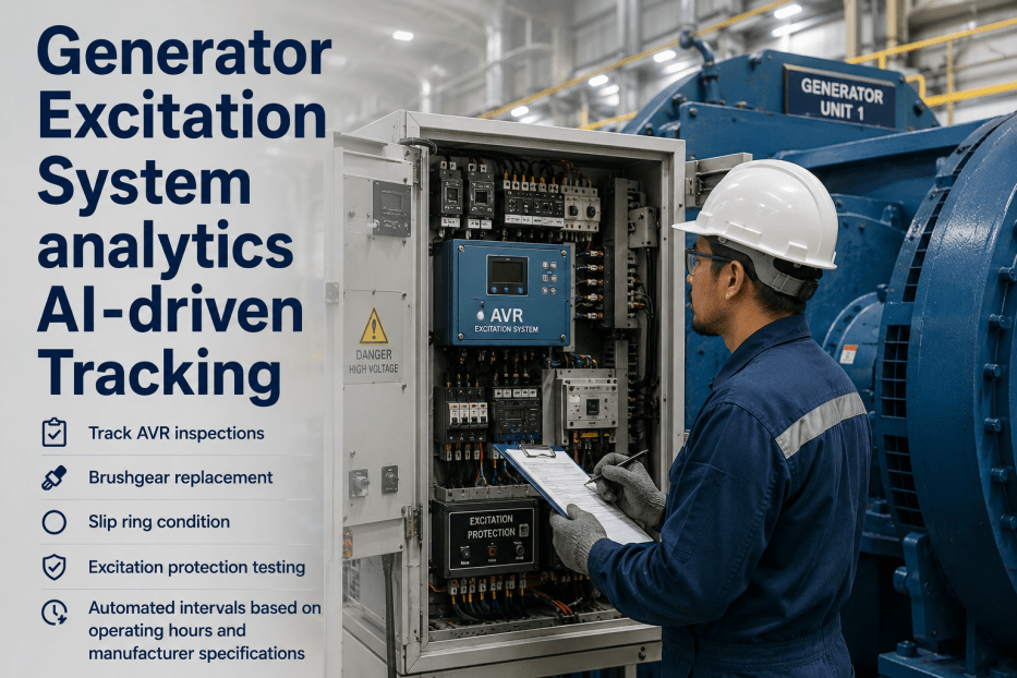
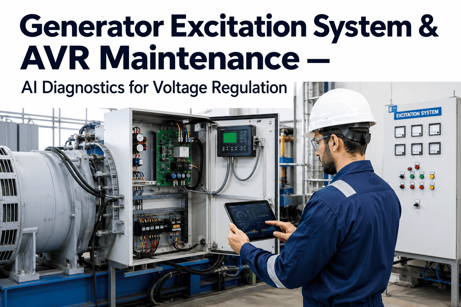
Generator Excitation System analytics AI-driven Tracking
By James Shakespeare on May 27, 2026
The excitation system is one of the most consequential — and most neglected — maintenance domains in power plant operations. When the Automatic Voltage Regulator drifts out of calibration it does so gradually and invisibly: reactive power swings that stress interconnected units, voltage instability that network operators can't initially trace to source, and eventually a protection relay trip that takes the unit off the grid without warning. When brushgear on a brushed exciter reaches end-of-life, the carbon dust contamination begins weeks before flash-over risk becomes critical — but without systematic slip ring inspection records and trending data, there is no early warning. When an excitation protection relay test is overdue, no alarm sounds in the control room: the gap only surfaces during a regulatory audit or, worse, after a protection failure. Excitation system failures account for approximately 8–12% of generator forced outages at thermal power plants — a disproportionately high contribution from a system that is technically straightforward to maintain when the maintenance program is properly managed. iFactory's AI-driven analytics platform manages every dimension of excitation system maintenance: AVR inspection and calibration tracking, brushgear condition and replacement scheduling, slip ring surface condition trending, and excitation protection testing intervals — all automated, all documented, all traceable for audit. For an immediate conversation about your excitation system maintenance program,
The Excitation Maintenance Gap — In Numbers
Why Excitation System Maintenance Fails — and What It Costs
8–12%
Of generator forced outages at thermal plants are traceable to excitation system failures — disproportionate to system complexity
60%
Of AVR calibration drift events are undetected until the unit's reactive power contribution shifts enough to be noticed by grid operators — not maintenance
3× faster
Brushgear wear rate in high-humidity and high-contamination environments versus manufacturer-rated life — making fixed-interval replacement systematically wrong
90%
Reduction in excitation-related forced outages documented at plants that deploy condition-based excitation maintenance programs vs. fixed-interval calendar programs
The Excitation System Reliability Problem
Excitation system maintenance fails for a simple reason: it is complex enough to require specialist knowledge for correct inspection, but simple enough that plant management treats it as a routine calendar item rather than a condition-monitored reliability program. The result is that AVR calibration drift accumulates between fixed annual inspections, brushgear wears at environment-dependent rates that calendars cannot account for, slip ring condition deteriorates gradually between manual rounds, and protection test intervals slip past their due dates without automated tracking. Every one of these failures is preventable with systematic, automated maintenance interval management. iFactory eliminates each gap by connecting excitation system inspection scheduling, condition records, and test documentation into a single platform that generates work orders, tracks completion, trends condition data, and produces audit-ready documentation automatically.
What Happens Without Condition-Based Excitation Management
Fixed-interval excitation maintenance assumes every generator operates in the same environment and experiences the same wear rates. A unit operating in a coastal high-humidity environment with elevated brush wear rates gets the same 12-month brushgear inspection interval as a unit in a clean, climate-controlled environment with minimal wear. The high-wear unit flashes over before its inspection is due. The low-wear unit gets unnecessary maintenance that consumes outage time and parts budget. Both outcomes are costly and preventable.
AVR drift undetected between annual checksBrushgear intervals ignore environmentProtection tests slip past due datesNo condition trending between inspections
iFactory AI-driven Program
Condition-Based Excitation Maintenance With Automated Interval Management
iFactory tracks operating hours, ambient conditions, and inspection results to calculate condition-appropriate maintenance intervals for each unit's excitation system individually. Brushgear intervals are adjusted based on actual wear rate data from successive inspections — not manufacturer defaults. AVR calibration checks are triggered by operating hours thresholds and flagged for early inspection when reactive power trends suggest drift. Protection test intervals generate automated work orders before due dates, with escalation if not completed on schedule.
Operating-hour-based AVR calibration triggersBrushgear intervals matched to actual wear rateProtection test auto-scheduling and escalationCondition trending between every inspection
Six Core Excitation Maintenance Functions
What iFactory Tracks and Manages Across Your Excitation System
Each function below addresses a specific excitation system maintenance requirement. Taken together, they constitute a complete condition-based excitation reliability program. Book a Demo to see how they apply to your generator fleet's specific excitation configuration.
01
AVR Inspection and Calibration Tracking
iFactory generates AVR inspection work orders based on operating hours thresholds and calendar intervals, whichever comes first. Calibration results — voltage set point accuracy, reactive droop settings, stability margins, and step response parameters — are recorded per inspection with trend analysis across successive tests. Drift from specification triggers early inspection alerts before it affects unit reactive power contribution or grid stability margins.
Impact: Eliminates undetected AVR drift
02
Brushgear Condition and Replacement Scheduling
For brush-type exciters, iFactory tracks brush length measurements at every inspection and calculates wear rate based on operating hours between measurements. Replacement work orders are generated when projected brush life reaches the minimum safe length threshold — not on a fixed calendar. Units in high-wear environments (humid climates, higher brush current density) automatically receive shorter inspection intervals based on actual wear rate data from successive inspections rather than manufacturer defaults.
Impact: Prevents flash-over from worn brushes
03
Slip Ring Surface Condition Trending
Slip ring condition — surface roughness, eccentricity, groove depth, contamination level, and discoloration patterns — is recorded at every brushgear inspection in a structured assessment format. Successive condition records are trended over time, with deterioration rate analysis flagging units where surface degradation is accelerating beyond normal wear progression. This trending identifies units approaching the threshold for slip ring resurfacing or replacement weeks before the condition becomes critical.
Impact: Identifies resurfacing need 4–8 weeks early
04
Excitation Protection Testing Intervals
Excitation system protection relays — field overcurrent, loss of field, over-excitation limiter, under-excitation limiter, and stator earth fault protection — require periodic functional testing to verify correct operation. iFactory generates protection test work orders per relay type on configurable intervals (typically 12–24 months depending on relay type and manufacturer specification) with advance notification at 30, 14, and 7 days before due date. Overdue tests escalate to the plant engineer and management. Test results are recorded per relay with pass/fail documentation and certificate reference numbers for regulatory audit.
Impact: Zero protection tests overdue without escalation
05
Excitation Transformer and Rectifier Analytics
For static excitation systems, iFactory tracks excitation transformer condition — oil sampling results, temperature differential trending, winding resistance tests — alongside rectifier bridge condition: thyristor firing angle balance, cooling system performance, and periodic diode health testing on brushless exciters. Transformer and rectifier maintenance intervals are integrated with the overall excitation maintenance program, ensuring the full excitation circuit is covered under a single managed maintenance record.
Impact: Full excitation circuit coverage in one platform
06
Regulatory Audit Documentation
iFactory generates audit-ready excitation system maintenance documentation automatically: AVR calibration certificates with date, technician, and parameter values; brushgear inspection records with measured brush lengths and wear rate calculations; slip ring condition reports with photographic reference capability; protection test certificates per relay with pass/fail outcomes and test equipment reference. All records are stored with timestamps, linked to the generator asset record, and exportable for NERC CIP, plant PMS audit, and insurance inspection requirements.
How iFactory Manages the Excitation Maintenance Cycle
From inspection scheduling through to audit documentation, this is the operational loop that ensures no excitation maintenance event is missed and every result is recorded and trended.
Step 01
Automated Work Order Generation
iFactory generates excitation maintenance work orders automatically based on each generator's configured maintenance intervals — operating hours for AVR calibration, condition-based wear rate projections for brushgear replacement, fixed intervals for protection relay testing. Work orders are generated at the defined advance notice period (typically 30 days for major AVR work, 14 days for routine inspections) with all relevant task details, required test equipment references, and safety isolation requirements pre-populated from iFactory's excitation work order templates. The responsible technician and approving engineer receive automatic notifications at generation, at 7 days, and on the due date.
Step 02
Structured Inspection Result Capture
When the technician completes the inspection or test, results are entered via iFactory's mobile interface directly at the excitation cubicle or brushgear access point — no deferred paperwork, no transcription to a CMMS later. AVR calibration records capture voltage set point, droop settings, and step response parameters. Brushgear inspections record measured brush lengths per brush position, slip ring surface condition rating, and carbon dust level. Protection test records capture relay identification, test type, as-found and as-left results, and pass/fail determination. All records are timestamped with the technician's authenticated user ID.
Step 03
Condition Trending and Interval Adjustment
After each inspection, iFactory's analytics layer processes the new results alongside the unit's inspection history. Brush wear rate is recalculated from the updated measurements and projected wear life is adjusted accordingly — if the latest inspection shows accelerated wear, the next inspection interval is automatically shortened to match the new projected wear rate. AVR calibration parameter trends are plotted across successive inspections, with statistical process control alerts flagging values that are trending toward specification limits even if they have not yet exceeded them. Slip ring condition score trends are tracked with deterioration rate flags. This continuous trending is what converts discrete inspection data points into a predictive maintenance capability.
Step 04
Audit Documentation and Compliance Reporting
All excitation maintenance records — AVR calibration certificates, brushgear inspection reports, slip ring condition assessments, protection test certificates, and corrective action close-outs — are compiled automatically into an excitation system maintenance audit package that is generated on demand. The package contains every record in chronological order, with technician authentication, timestamps, and cross-references between inspection findings and corrective actions. For NERC CIP facilities, excitation protection documentation is formatted to align with CIP-007 and CIP-014 maintenance record requirements. For insurance audit, the package demonstrates continuous maintenance program execution with no gaps in the inspection record. Book a Demo to see the audit documentation package for your specific generator fleet configuration.
See iFactory's Excitation System Analytics Live
30-Minute Demo: AVR Tracking, Brushgear Condition Trending, and Protection Test Management Applied to Your Generator Fleet
We walk through iFactory's excitation maintenance dashboard — showing AVR calibration history, brush wear rate calculations, slip ring condition trends, and protection test scheduling. You see exactly how the platform manages your specific excitation configuration and what the audit documentation package looks like for your regulatory reporting obligations.
Calendar-Based vs. iFactory Condition-Based: The Excitation Maintenance Performance Gap
Side-by-side performance comparison between fixed-interval calendar maintenance and iFactory's condition-based excitation maintenance program, based on EPRI reliability data and documented iFactory deployment outcomes at thermal power generation facilities.
Excitation System Maintenance Program Comparison
Maintenance Dimension
Calendar-Based Program
iFactory Condition-Based
Outcome Difference
AVR Inspection Trigger
Fixed annual interval regardless of operating hours or performance signals
Operating hours + reactive power trend monitoring
Drift detected before grid operator notice
Brushgear Replacement Interval
Fixed interval — same for high-wear and low-wear environments
8–12% of total generator forced outages (EPRI baseline)
80–90% reduction in excitation-related forced outages
Direct availability factor improvement
Audit Documentation
Manual compilation 2–5 days before audit — gaps likely
On-demand generation in minutes — complete and traceable
Days to minutes, no documentation gaps
Multi-Unit Fleet Management
Each unit managed independently — no fleet-level visibility
Fleet-wide excitation status dashboard with risk ranking
Prioritized attention across entire generator fleet
Expert Perspective: What Excitation Specialists Say About Systematic Maintenance Tracking
Power plant protection and excitation engineers who have moved from calendar-based to condition-based excitation maintenance programs consistently identify the same operational improvements and the same organizational barriers that delay the transition.
The most dangerous assumption in excitation system maintenance is that annual inspection is sufficient protection against AVR drift and brushgear degradation. It is not — and the reason is simple: both failure modes develop on timescales that are shorter than annual inspection intervals in real operating environments. AVR calibration can drift meaningfully in 6,000 operating hours. Brushgear in a coastal or high-humidity environment can approach end-of-life in 4,000 hours rather than the 8,000 hours the manufacturer's datasheet suggests. If your inspection interval is not matched to your actual degradation rate, you are running a reliability program that is systematically wrong by design. The second issue I see consistently is protection relay test management. Every plant I've worked at has had at least one protection test that was overdue when we checked — not because engineers were negligent, but because there was no automated system generating the reminder and escalating it if the test wasn't completed. Manual tracking in a spreadsheet requires someone to look at the spreadsheet, and in a busy plant that doesn't always happen on schedule. The financial case for an automated system is straightforward: a single excitation-related forced outage on a 400 MW unit costs $500,000–$1,500,000 in replacement power and repair costs. A platform that prevents one outage per year pays for itself many times over. The case is obvious. What's surprising is how many plants are still running calendar-based programs when condition-based tools are available and affordable.
Chief Protection and Excitation Engineer, Major U.S. Utility21 Years Power Plant Protection Engineering · Former IEEE Power System Relaying Committee Member · Cigré Working Group B3 (Substations) · Three-Time EPRI Excitation System Reliability Workshop Presenter · Author, Utility Internal Excitation Maintenance Standard
90%
Reduction in excitation-related forced outages at plants with condition-based excitation programs
100%
Protection test documentation completeness with automated scheduling and escalation
4–8 wk
Earlier slip ring resurfacing identification via condition trending vs. qualitative inspection
70%
Reduction in over-maintenance waste from condition-based vs. fixed-interval brushgear replacement
Book a Demo to see how iFactory's excitation system analytics applies to your specific generator fleet — brushed or brushless, static or rotating exciter, any manufacturer configuration.
What iFactory's Excitation System Analytics Delivers
Purpose-built for power generation excitation maintenance — not generic asset management retrofitted for the application.
AVR Analytics
Operating-Hour AVR Calibration Tracking with Parameter Trending
AVR inspection work orders generated on operating hours thresholds. Calibration parameters trended across successive tests. Drift-toward-limit alerts before specification exceedance. Calibration certificates generated automatically for audit.
Brushgear Management
Wear-Rate-Based Brushgear Scheduling with Slip Ring Condition Trending
Brush length measurements tracked per position. Wear rate calculated from successive inspections. Replacement work orders generated at projected minimum-safe-length threshold. Slip ring surface condition scored and trended over time with deterioration rate alerts.
Protection Management
Automated Protection Test Scheduling with Escalation and Certificate Documentation
Protection relay test work orders per relay type on configurable intervals. 30/14/7-day advance notifications. Overdue escalation to engineer and management. Pass/fail test results with certificate reference stored per relay and exportable for NERC CIP and regulatory audit.
Compliance & Fleet
Fleet Excitation Status Dashboard with On-Demand Audit Documentation
Generator fleet view showing each unit's excitation maintenance status, overdue items, and next scheduled activities. Risk-ranked unit listing identifying which generators have the highest excitation maintenance risk. Full audit documentation package generated on demand in minutes.
Conclusion — Start Your Excitation Analytics Program Today
iFactory Excitation System Analytics — Condition-Based Management for Every Generator on Your Fleet
Excitation system failures account for 8–12% of generator forced outages at thermal plants — and 90% of them are preventable with systematic condition-based maintenance. iFactory eliminates fixed-interval scheduling guesswork by connecting operating hours data, condition inspection results, and protection test records into a single platform that generates work orders, trends condition data, escalates overdue items, and produces audit-ready documentation automatically. No excitation maintenance event is missed. No regulatory gap is created. No inspection result is untrended.
Operating-hour AVR calibration tracking and parameter trending
Wear-rate brushgear scheduling and slip ring condition trending
Automated protection relay test scheduling with escalation
On-demand audit documentation for NERC CIP and regulatory review
Frequently Asked Questions — Excitation System Analytics
Does iFactory support both brushed and brushless excitation systems?
Yes. iFactory's excitation system analytics covers all major excitation configurations used in power generation. For brushed excitation systems — both DC commutator exciters and AC exciters with rotating rectifiers — the platform manages brushgear inspection scheduling, brush length measurement tracking, slip ring condition assessment, and wear rate calculation. For brushless excitation systems (rotating rectifier configurations), brushgear management is replaced by rotating diode health monitoring and rectifier bridge condition tracking. For static excitation systems (STATIC or thyristor-controlled), the platform manages AVR calibration tracking, excitation transformer condition, and thyristor firing angle monitoring. The asset configuration in iFactory specifies the excitation type for each generator, and the maintenance program templates are automatically adapted to the correct inspection tasks for that configuration. Book a Demo to confirm the specific maintenance template for your generator fleet's excitation types.
How does iFactory calculate condition-appropriate brushgear replacement intervals rather than using manufacturer defaults?
iFactory calculates wear rate from measured brush length data across successive inspections. At each brushgear inspection, the technician records the measured length of each brush at each position in the brush holder. iFactory calculates the wear since the previous inspection in millimetres per operating hour (or per calendar day if operating hours data is not available from the DCS historian). From this actual wear rate, the platform projects the number of operating hours before each brush reaches the configured minimum safe length threshold — typically 25–30% of new brush length, depending on brush type and manufacturer specification. A replacement work order is generated at the calculated remaining life threshold rather than on a fixed calendar interval. For brushes wearing faster than expected — due to elevated humidity, contamination, high brush current density, or spring pressure variation — the replacement work order is generated earlier. For brushes wearing slower than expected, the interval extends accordingly. This prevents both the flash-over risk of allowing worn brushes to run past their safe life and the unnecessary maintenance cost of replacing brushes with significant remaining useful life on a fixed calendar.
Which excitation protection relay types and tests does iFactory's protection test management cover?
iFactory's protection test management is configurable to any protection relay type associated with the excitation system. Standard excitation protection types that iFactory's default templates cover include: Loss of Field protection (40Q), Over-Excitation limiter function test (UEL/OEL), Field overcurrent protection (64F), Stator earth fault protection as it relates to excitation circuit (64), V/Hz limiter and protection function test, AVR manual/auto transfer test, and excitation system trip and interlock verification. Each relay type is assigned a configurable test interval (typically 12–24 months depending on relay type, age, and regulatory jurisdiction requirements). iFactory generates a separate work order per relay type per test cycle, with specific test requirements populated from the template. Test results are recorded per relay with as-found and as-left readings where applicable, pass/fail determination, and test equipment reference. For plants operating under NERC CIP requirements, protection test documentation is structured to align with CIP maintenance record requirements. The relay template library is configurable to any generator protection standard specific to your jurisdiction or OEM specification.
How does iFactory detect AVR calibration drift between scheduled inspections?
iFactory uses two complementary methods for between-inspection AVR drift detection. First, operating hours tracking: iFactory reads the generator's running hours from the DCS historian or SCADA system (via OPC-UA or PI System connection) and generates an early-inspection alert when operating hours since the last AVR calibration approach the configured threshold — even if the calendar date for the next scheduled inspection has not yet arrived. For generators that run at high capacity factors, operating hours-triggered inspections may occur significantly more frequently than annual calendar intervals. Second, reactive power performance monitoring: for plants where reactive power output data is available from the DCS historian, iFactory monitors trends in each generator's reactive power contribution at comparable loading conditions across successive operating periods. Statistically significant drift in reactive power output at similar load conditions is flagged as a potential indicator of AVR setpoint drift and triggers an early inspection recommendation. This reactive power trend monitoring does not replace scheduled AVR calibration but provides an additional detection layer between scheduled inspections. Book a demo to discuss the specific monitoring options for your DCS historian integration.
How long does it take to deploy iFactory's excitation system analytics for a power plant fleet?
iFactory's excitation system analytics deployment follows the same staged timeline as the broader power plant analytics program. The excitation-specific configuration — asset hierarchy with excitation type specification, maintenance interval configuration per unit, protection relay type and test interval setup, and historical calibration and inspection data migration — is typically completed within the first 30 days of the overall plant deployment. For a plant with 4–6 generating units, initial work order generation for AVR calibration and brushgear inspection typically begins within 2 weeks of excitation asset configuration. Protection test management is configured and active within 3–4 weeks. Historical inspection data migration from existing CMMS or spreadsheet records — which provides the historical baseline for wear rate calculation and condition trending — is completed within the first 30 days alongside the broader migration scope. The full excitation analytics capability, including condition trending and interval adjustment from the first post-deployment inspection results, is typically operational within 60 days of deployment start. Book a Demo to see the deployment timeline for your specific generator fleet size and excitation configuration mix.