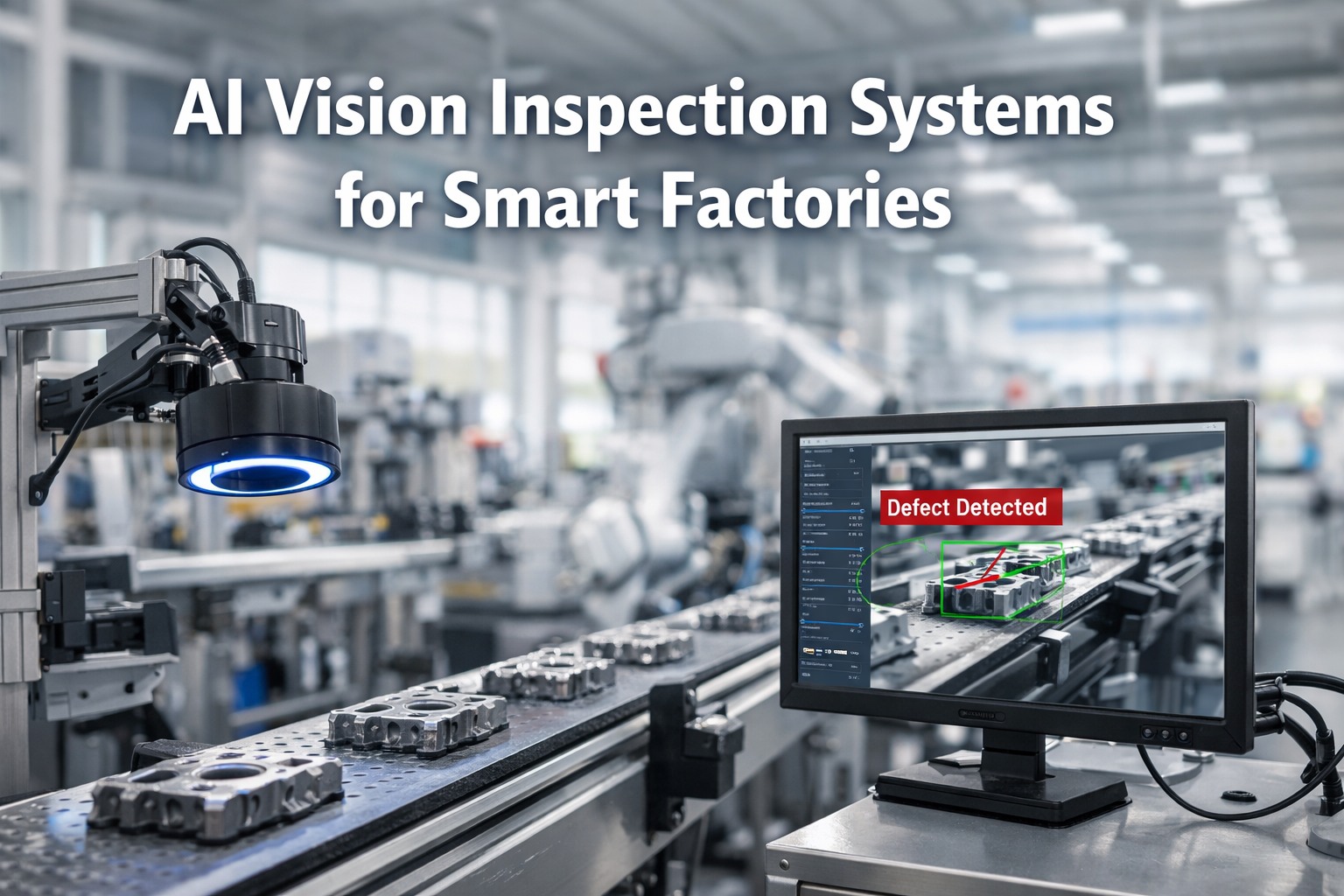
Single-camera inspection is a lie of omission. It inspects what it can see and ignores everything else — curved surfaces, recessed features, underside geometry, weld joints at oblique angles, and any surface not perpendicular to the lens axis. For simple flat parts, one camera works. For anything with three-dimensional complexity — automotive castings, machined housings, electronic assemblies, medical devices, consumer products with multiple faces — single-camera inspection misses 15-40% of the surface area entirely. I've audited hundreds of inspection stations over twenty years, and the pattern is always the same: a single camera catches the obvious top-surface defects, and every other defect escapes to the customer. The fix isn't just "add more cameras." It's engineering: calculating the optimal number of cameras and angles from the product geometry, designing synchronized triggering so all views capture the same product at the same instant, building a multi-view AI pipeline that fuses information from all cameras into a single classification decision in under 100ms, and integrating the physical station — mounting structures, lighting arrays, cable management, reject mechanisms — into the production line layout during the greenfield phase. Adding cameras after construction means custom brackets welded to finished structures, cables routed through completed ceilings, and synchronization hacked together with daisy-chained trigger cables that drift. We design it right from the start. Schedule a Demo
The Single-Camera Blind Spot Problem
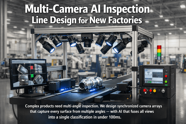
Missing defects on hidden surfaces? Schedule a demo to see how multi-camera arrays eliminate blind spots and catch the 15-40% of defects that single-camera systems miss entirely.
Product Geometry to Camera Count
| Product Geometry | Cameras Required | Typical Angles | Lighting Per Camera | Cycle Time Impact | Example Products |
|---|---|---|---|---|---|
| Flat / 2D | 1-2 (top + optional bottom) | 0° top, 180° bottom | Backlight or diffuse bar | None — inline linescan | Sheet metal, PCBs, labels, film |
| Prismatic / Box | 4-6 (top + 4 sides + bottom) | 0°, 90° × 4, 180° | Bar light per face, angled 30-45° | +0.5-1s for rotation or multi-station | Machined blocks, enclosures, cartons |
| Cylindrical | 3-4 + rotation stage | 0° top, 90° side × 2-3, 360° rotation | Line light with rotation sync | +1-3s for full rotation scan | Shafts, pistons, bottles, cans |
| Complex 3D | 8-16 (multi-angle dome) | 0°, 45° × 4, 90° × 4, 135° × 4, 180° | Dome or multi-ring structured light | +0.5-2s for all captures | Castings, turbine blades, medical implants |
| Assembly / Multi-Part | 12-32 (zone-specific arrays) | Product-specific per zone | Zone-specific (BF/DF/coaxial mix) | +2-5s for sequential zone capture | Engine assemblies, electronics, consumer devices |
Synchronization Architecture
All cameras, frame grabbers, and lighting controllers synchronized to a common PTP grandmaster clock. Time accuracy: ±100 nanoseconds across all devices. Every image from every camera carries a PTP timestamp — enabling pixel-accurate correlation between views. PTP grandmaster specified in the network architecture; PTP-capable GigE Vision or CoaXPress cameras specified in the machine purchase order. Without PTP, multi-camera correlation relies on trigger cable daisy-chains that accumulate jitter and drift — unusable for moving products.
Product detection sensor (photoelectric or proximity) triggers all cameras simultaneously via hardware trigger line. For conveyor-mounted inspection, encoder pulses from the conveyor drive trigger linescan cameras at precise spatial intervals. Trigger distribution: dedicated trigger distribution board (not PLC digital outputs, which have 1-5ms jitter). All trigger wiring in shielded twisted pair with dedicated conduit — no shared cable trays with VFD power cables.
Each camera's LED lighting fires in sync with the camera exposure — strobe duration matched to exposure time (typically 10-500μs). Strobe controller receives trigger from same distribution board as cameras. Multi-angle stations with different lighting requirements (brightfield, darkfield, dome, backlight) fire sequentially within the inspection cycle — each camera + lighting pair captures independently, then AI fuses all views. Sequential firing eliminates cross-illumination interference between stations.
All camera images from one trigger event are assembled into a multi-view tensor on the edge GPU. CNN/Vision Transformer model processes all views simultaneously — not sequentially. The model learns which views are most informative for each defect type: top camera detects surface scratches, side cameras detect edge chips, bottom camera detects machining marks, angled cameras detect casting porosity. Final classification: single pass/fail decision with defect type, location (mapped to 3D product coordinates), and severity. Total inference time: <100ms for up to 16 simultaneous views on NVIDIA L4 GPU.
Physical Station Design
Mechanical Frame
Welded steel or extruded aluminum profile frame with vibration-isolated feet. Camera mounting rails with fine-adjustment (X/Y/Z + tilt/pan) for each camera position. All mounting points specified on station assembly drawings during greenfield design. Frame designed for product changeover: camera positions adjustable without tools for different product geometries. Light-sealed enclosure with matte black interior to eliminate stray reflections. Access panels for camera and lighting maintenance without production interruption.
Lighting Integration
Each camera paired with its own lighting array — no shared illumination between views. Lighting type matched to surface and defect: brightfield for scratches/stains, darkfield for bumps/dents, dome for curved/reflective surfaces, backlight for edge profile/holes, structured light for 3D surface topology. LED drivers mounted inside station enclosure with thermal management. Lighting intensity digitally controllable per product recipe — different products require different illumination profiles.
Cable Management
All camera data cables (GigE Vision, CoaXPress), trigger cables, power cables, and lighting control cables pre-routed through dedicated cable channels inside the station frame. Cable lengths specified at station design — no excess cable coiled inside panels. Fiber patch panels at station base for network connection to edge compute rack. All connections labeled and documented in station cable schedule. Greenfield advantage: cable drops from overhead tray pre-positioned directly above each station location.
Reject Mechanism
Integrated reject mechanism triggered by AI classification result. Mechanism type matched to product and line: pneumatic pusher (small parts on conveyor), diverter gate (larger products), robotic pick-and-place (high-value or fragile products), ink-mark for downstream manual sort. Reject bin with counter and overflow sensor. PLC interlock: reject mechanism confirmed before next product enters inspection zone. Reject images archived with full multi-view gallery for quality review and model retraining.
Need a multi-camera inspection station designed into your production line? Schedule a demo to see station layouts, camera count optimization, and multi-view AI fusion for your specific product geometry.
Edge GPU Sizing for Multi-Stream
| Station Configuration | Camera Count | Total Data Rate | GPU Required | Inference Latency | Power / Cooling |
|---|---|---|---|---|---|
| Small: Flat/Prismatic | 2-4 cameras | 0.5-2 GB/s | NVIDIA Jetson Orin or L4 | <30ms | 15-72W; passive/fan cooling |
| Medium: Cylindrical/3D | 4-8 cameras | 2-4 GB/s | NVIDIA L4 or A2 | <50ms | 40-72W; active fan cooling |
| Large: Complex Assembly | 8-16 cameras | 4-8 GB/s | NVIDIA L40S | <80ms | 350W; server rack with cooling |
| Enterprise: Multi-Station | 16-32 cameras (across stations) | 8-16 GB/s | NVIDIA L40S × 2 or H100 | <100ms | 350-700W; dedicated compute rack |
Multi-View AI Pipeline
Each camera image independently preprocessed: flat-field correction (removes lens vignetting), geometric undistortion (removes lens barrel/pincushion), ROI extraction (isolates product from background), and normalization (consistent brightness/contrast across cameras). Preprocessing runs on frame grabber FPGA — zero GPU load.
Shared CNN backbone (ResNet-50 or EfficientNet-B3) extracts feature maps from each view independently. Backbone weights shared across all views — the same feature extractor processes top, side, bottom, and angled views. Reduces model size by 60-80% vs independent models per camera. Feature maps: 2048-dimensional vector per view.
Feature vectors from all views concatenated and processed by a fusion network (attention-based transformer or multi-head attention layer). The fusion network learns which views are most informative for each defect type — automatically weighting the bottom camera higher for machining defects and side cameras higher for edge chips. Cross-view attention discovers correlations between views: a surface anomaly visible in one view confirmed or rejected by adjacent views.
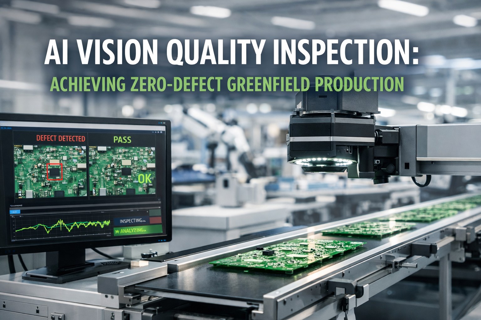
Single classification head outputs: pass/fail, defect type (from 50+ class taxonomy), severity (cosmetic/functional/critical), and 3D location on product surface (mapped from 2D image coordinates via calibration matrices). One report per product unit — not per camera. Defect gallery shows all views with defect highlighted. Full traceability: product serial + timestamp + all images + classification + confidence score.
Key Benefits & ROI
One Camera Sees One Side. Eight Cameras See Everything.
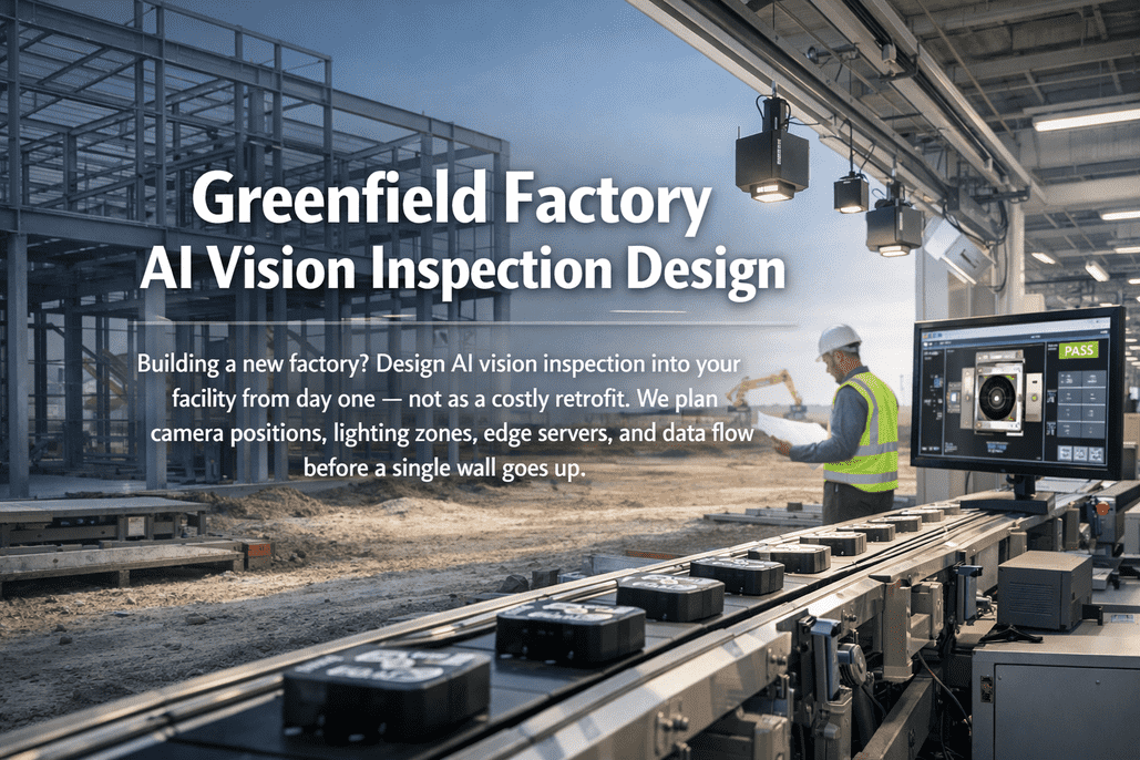
iFactory designs multi-camera AI inspection stations for greenfield factories — synchronized arrays, multi-angle lighting, multi-view AI fusion, and reject integration — engineered into the line layout and operational from the first product.
Frequently Asked Questions
Greenfield: $15K-$40K Per Station. Retrofit: $50K-$150K.
Camera mounting structures, lighting enclosures, cable drops, and trigger distribution — all trivial during construction. All expensive after the ceiling is closed and the line is running.