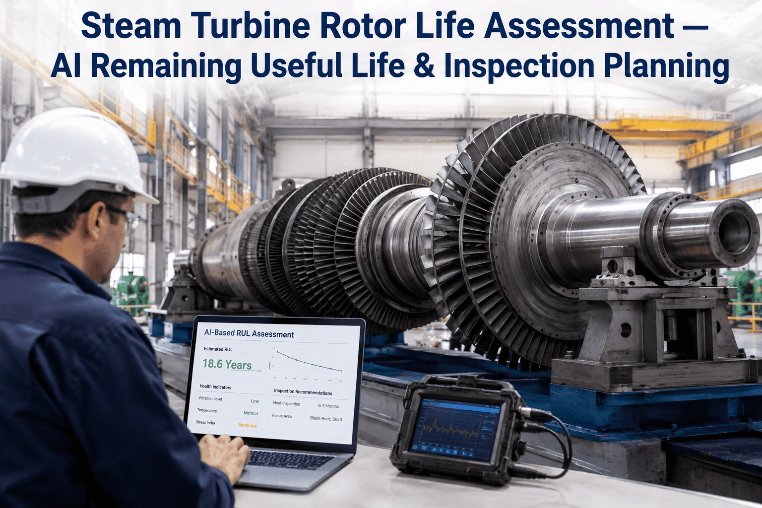
Steam turbine rotors operate under extreme combinations of temperature, pressure, and centrifugal stress for decades, and most reliability engineers still estimate remaining useful life by manually combining startup cycle counts with conservative handbook curves that were never calibrated to their specific unit. The result is either a premature rotor replacement costing millions or an unexpected creep crack that forces an emergency outage during peak season. AI-driven rotor life assessment changes this by correlating your actual operational stress history, metallurgical condition data, and real-time performance parameters into a continuous remaining useful life model that evolves with every operating hour. You can book a demo to see how your rotor data feeds into a live RUL model.
Your Turbine Rotor Has Been Accumulating Damage Every Start-Stop Cycle — Most Plants Still Estimate the Total Blindly
iFactory builds a continuously updating remaining useful life model from your rotor's actual stress history, metallurgical condition, and operating parameters, replacing handbook estimates with evidence you can defend to your insurance carrier and your management.
What Blind Life Assessment Actually Costs a Power Plant
When remaining useful life is estimated from generic curves rather than unit-specific data, the financial consequences compound across every decision point from inspection scheduling to capital planning. The figures below represent typical impacts reported by reliability engineering teams operating large steam turbines in base-load and cycling service.
Where Creep, Fatigue, and Their Interaction Actually Damage Your Rotor
Steam turbine rotor life is governed by two competing degradation mechanisms whose relative severity depends on operating temperature and cycle frequency. Understanding which zone your rotor operates in determines what data matters most for life assessment and where inspection should focus.
Why Handbook Curves Leave Most of Your Rotor Data Unused
Traditional life assessment relies on standardized material properties and simplified stress assumptions that ignore the specific loading history of your rotor. An AI-powered model ingests the same data plus everything the handbook method discards, producing a remaining useful life estimate that narrows the uncertainty band significantly.
| Assessment Parameter | Traditional Method | AI-Powered RUL Model |
|---|---|---|
| Data Source | Handbook curves and manual cycle count from operator logs | Operational history, metallurgical findings, and real-time performance data combined |
| Creep Estimation | Larson-Miller parameter with assumed uniform stress distribution | Actual stress from finite element correlation with recorded load and temperature profiles |
| Fatigue Estimation | Generic S-N curves for the material class with standard safety factors | Cycle-specific strain range calculated from recorded startup and shutdown thermal profiles |
| Interaction Model | Linear damage summation, widely acknowledged as overly conservative | Non-linear creep-fatigue interaction model trained on bore sample metallurgical data |
| Update Frequency | Recalculated at each major overhaul, typically every 3 to 5 years | Continuously updated with each operating hour and every new data point ingested |
| Inspection Planning | Fixed interval borescope and replication regardless of accumulated damage rate | Condition-triggered inspection with risk-prioritized scope based on predicted damage location |
| RUL Uncertainty | 30 to 50 percent of predicted remaining life | 10 to 15 percent of predicted remaining life with confidence intervals |
| Decision Output | Binary replace or run to next outage recommendation | Optimized timeline with run-extend-replace scenarios and associated confidence levels |
What the Model Needs to Build an Accurate Rotor Life Picture
The accuracy of any remaining useful life model depends entirely on the quality and specificity of the data fed into it. The five categories below represent the inputs that separate a genuinely predictive model from a dressed-up spreadsheet, and most plants already have most of this data sitting in separate systems that have never been combined.
Operational Stress History
Recorded startup and shutdown thermal profiles, load swing magnitude and frequency, overspeed event logs, and temperature ramp rates extracted from DCS historian archives spanning the rotor's entire service life.
Metallurgical Condition Data
Bore replication results, hardness traverse measurements, borescope findings with location mapping, and any destructive test results from previous overhauls that provide direct evidence of microstructural degradation state.
Real-Time Performance Parameters
Live vibration signatures, exhaust temperature distributions, steam purity indicators, and bearing oil temperature trends that serve as leading indicators of changing rotor condition between inspection intervals.
Design and Material Records
Original rotor forging specifications, material grade and heat treatment records, geometric dimensions from manufacturing drawings, and as-built tolerances that define the baseline for stress analysis and damage modeling.
Maintenance and Environmental History
Water chemistry logs, previous repair or weld repair records, any abnormal operating events like water induction or gland seal failures, and complete overhaul history with findings documented at each inspection.
A Rotor Life Estimate Based on Generic Curves Is an Opinion, Not an Assessment
iFactory's AI RUL model replaces handbook assumptions with your rotor's actual operational and metallurgical data, delivering a continuously updated remaining useful life estimate with quantified confidence intervals.
From Raw Rotor Data to a Prioritized Inspection Plan
The AI RUL model does not produce a single life number and stop. It generates a spatial damage map across the rotor geometry that tells your inspection team exactly where to look, what to look for, and how much remaining life those specific locations have before the next scheduled inspection window.
Historical Data Ingestion
Decades of DCS historian data, overhaul reports, and metallurgical records are ingested and structured into a unified rotor-specific dataset that becomes the foundation for all subsequent modeling work.
Damage Model Calibration
The creep-fatigue damage model is calibrated against actual metallurgical findings from bore samples and replication results so the simulation matches measured degradation rather than theoretical predictions.
Continuous RUL Computation
The calibrated model runs continuously against live operational data, updating the remaining useful life estimate and damage distribution map as each new operating hour accumulates on the rotor.
Inspection Trigger Planning
When predicted damage at any rotor location approaches a threshold, the system generates a prioritized inspection scope with specific locations, recommended NDT methods, and expected findings.
What Reliability Teams Report After AI RUL Model Deployment
The outcomes below reflect results reported by power generation and industrial steam users after deploying AI-driven rotor remaining useful life models on large steam turbines operating in both base-load and two-shift cycling service.
Questions Reliability Engineers Ask About AI Rotor Life Assessment
Stop Guessing Your Rotor's Remaining Life From Curves Written for Someone Else's Machine
iFactory's AI RUL model builds a rotor-specific life assessment from your actual operating data and metallurgical findings, updating continuously so every inspection and capital decision is backed by evidence you can trace and defend.