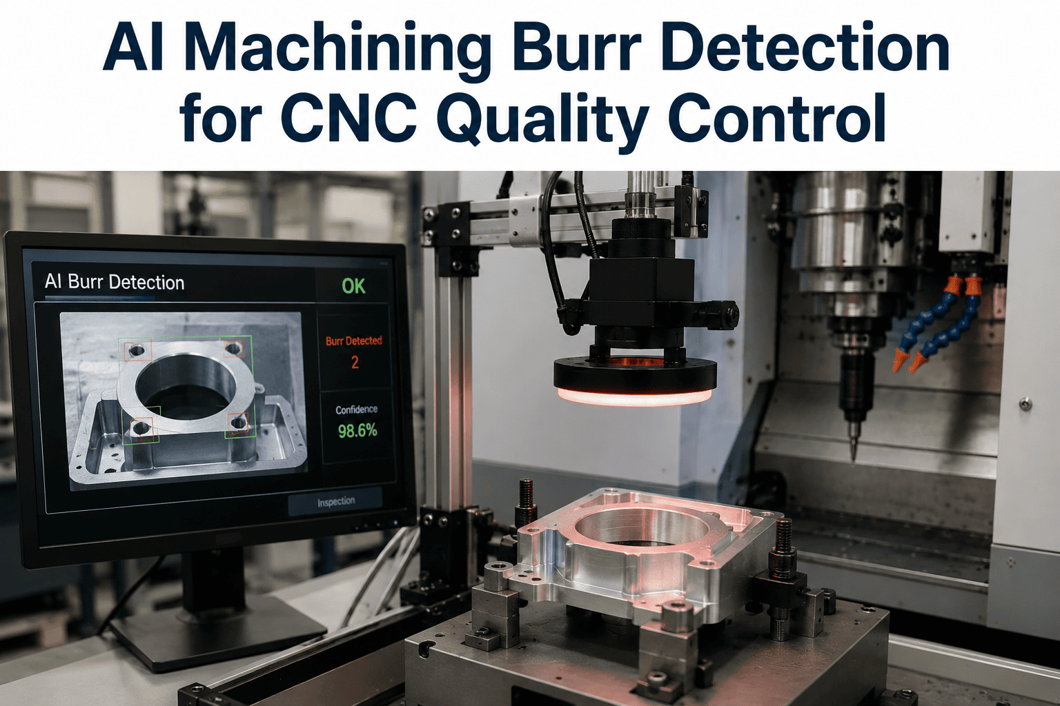
CNC machining sits at the precision end of manufacturing — where a $400,000 five-axis machining center is expected to hold dimensional tolerances measured in microns, run unattended across two shifts and produce parts that go directly into aerospace assemblies, medical devices, and defense components without secondary inspection. The question U.S. manufacturers are increasingly confronting is not whether their CNC machines are running — their SCADA systems answer that question — but whether those machines are running within the process window that actually produces conforming parts. Spindle load that is 15% above baseline tells you a tool is wearing toward failure before the tool actually breaks. Vibration frequency in the 800–1200 Hz range tells you chatter is developing before it damages the workpiece surface finish. An in-process probe measurement that shows a bore drifting 4 microns per hour tells you thermal growth is affecting your dimensional capability before the first out-of-tolerance part is produced. None of these signals are visible in a conventional uptime dashboard. All of them are visible — and actionable — in iFactory's CNC machine monitoring platform, which integrates spindle load, vibration, thermal compensation data, tool life counters, and in-process probe results into a unified real-time OEE and process health dashboard. Facilities using iFactory's CNC monitoring report 58% reduction in unplanned tool breakage events, 44% improvement in first-pass yield on tight-tolerance features, and 67% faster response to dimensional drift before out-of-tolerance production occurs.
CNC Machine Monitoring: Spindle Load, Tool Wear & Micro-Tolerance Control
iFactory's CNC monitoring platform goes beyond uptime — integrating spindle load, tool wear signals, chatter detection, and in-process dimensional data into a single real-time dashboard that connects machining process health to quality outcomes and OEE performance.
Why Uptime Monitoring Is Not Enough for CNC Process Control
A CNC machine that is "running" is not necessarily producing conforming parts. The gap between machine availability and dimensional conformance is where the most costly quality escapes in precision machining occur — and it is the gap that conventional uptime-based OEE monitoring cannot close. The five failure modes below define where CNC monitoring needs to go beyond run/stop status to deliver real process control value.
Progressive Tool Wear Without Load Signal Tracking
Tool wear in milling and turning operations follows a predictable load signature — spindle current rises gradually as the cutting edge degrades, then increases sharply as the tool approaches failure. Facilities that replace tools on fixed cycle counts rather than load-based wear curves either change tools too early, wasting tool life, or too late, risking catastrophic tool breakage and workpiece scrapping. Spindle load monitoring tracks the actual wear curve for each tool in each material, enabling replacement at the optimal point regardless of cycle count variability.
Chatter Development Undetected Until Surface Finish Failure
Machining chatter — resonant vibration between the cutting tool and workpiece — develops progressively before it produces visible surface damage. The vibration signature of developing chatter is detectable in the 500–2000 Hz frequency range 30 to 90 seconds before the workpiece surface finish degrades below specification. Accelerometer-based chatter detection integrated into iFactory's monitoring platform identifies the frequency signature and alerts the operator or adjusts spindle speed via CNC macro before the surface is damaged.
Thermal Growth Causing Dimensional Drift Across Long Runs
Machining center spindles and structural elements expand as thermal equilibrium is reached — a 5°C spindle temperature rise in a 400mm spindle produces approximately 8 microns of axial growth. On tolerance features of ±10 microns, uncompensated thermal growth can consume most of the tolerance budget within the first hour of the shift. In-process probing results integrated into iFactory's monitoring platform track dimensional drift in real time, triggering tool length offset corrections before the part moves out of tolerance.
OEE Calculated Without Process Yield Component
Standard OEE calculations multiply availability, performance, and quality — but in most CNC environments, the quality factor is calculated from end-of-batch inspection data, not from in-process measurements. A machine running at 95% availability and 98% performance with a first-pass yield of 88% has an OEE of 81.5% — but that quality figure only becomes visible after the batch is complete. iFactory's CNC OEE dashboard incorporates in-process probe data and real-time dimensional conformance tracking, making the quality component of OEE visible during the run rather than after it.
iFactory CNC Monitoring Platform: Four Integrated Signal Layers
iFactory's CNC machine monitoring platform integrates four distinct signal layers — spindle load, vibration/chatter, in-process probing, and thermal/environmental data — into a unified real-time dashboard that connects every measurable process variable to dimensional outcomes and OEE performance. Book a Demo to see iFactory's CNC monitoring configured for your machining center portfolio and part family tolerance requirements.
Spindle Load Monitoring — Real-Time Current Signature Analysis for Tool State and Spindle Health
iFactory's spindle load monitoring captures spindle motor current at 100ms sampling intervals — integrating with MTConnect-enabled controllers (Fanuc, Siemens, Heidenhain, Mazak, Okuma) and with legacy machines via current transducer retrofit. The current signature for each tool-material combination is baselined during an initial run period, establishing the expected load envelope for normal tool condition. Deviations above the upper load threshold trigger tool wear alerts; deviations below the lower threshold flag potential tool breakage, missing insert, or incorrect material. Spindle bearing condition monitoring uses high-frequency vibration analysis to detect bearing defect signatures, enabling predictive maintenance scheduling before bearing failure produces an unplanned outage.
Tool Wear Detection — Load-Based Remaining Life Prediction Across High-Mix Part Programs
iFactory's tool wear detection module tracks the spindle load signature for each tool across its operational life — building a wear curve that reflects actual cutting conditions rather than theoretical tool life estimates. As a tool wears, its load signature shifts upward; iFactory's model tracks the slope of that shift and projects the remaining cycles before the tool reaches the pre-set wear threshold. Replacement alerts are generated with enough lead time for the operator to prepare the replacement tool without interrupting the current cycle. For high-mix environments where each part number uses a different tool-material combination, the wear model adapts independently for each combination, eliminating the inaccuracy of applying a single cycle-count rule across diverse work.
In-Process Probing Integration — Real-Time Dimensional Data for Thermal Drift and Feature Conformance
iFactory integrates with on-machine probing systems (Renishaw, Blum, Marposs, Hexagon) to capture in-process dimensional measurements at configured intervals during the machining cycle. Probe results are fed into iFactory's monitoring platform in real time, where they are compared against nominal and tolerance limits with automated SPC analysis. Dimensional drift trends — the gradual movement of a measured feature away from nominal over successive parts — are visualized as control charts that show both the current part's position within tolerance and the trend direction. When drift velocity indicates that the feature will reach the tolerance boundary within a configured number of parts, iFactory generates a corrective action alert — triggering an operator notification or automatically writing a tool length offset correction to the CNC controller via macro variable interface.
Real-Time OEE Dashboard — Availability, Performance, and In-Process Quality on a Single Screen
iFactory's CNC OEE dashboard calculates and displays availability, performance, and quality metrics in real time — updating every cycle rather than at end-of-shift or end-of-batch. The quality component of OEE is calculated from in-process probe data and in-cycle anomaly events rather than from end-of-batch CMM results, making the quality factor actionable during production rather than retrospective. The dashboard is configurable at the machine, cell, department, and plant level — allowing a manufacturing engineer to view a single machine's process signature while a plant manager views aggregate OEE across 40 machining centers. Downtime events are automatically categorized by signal — spindle fault, axis alarm, tool change, program hold, material wait — reducing the manual downtime coding burden and improving the accuracy of downtime root cause data.
CNC Monitoring Signal-to-Action Workflow: From Sensor Reading to Corrective Response
The operational value of CNC monitoring is determined not by the number of signals collected but by the speed and reliability of the corrective action each signal triggers. The workflow below traces the path from raw signal to corrective action for the four most operationally significant monitoring events in a precision machining environment.
CNC Monitoring Deployment Outcomes: Performance Comparison Across Machining Environments
The table below presents measured outcomes from iFactory CNC monitoring deployments across aerospace, medical device, and general precision machining environments. All figures reflect actual operational improvements measured over a 6 to 12 month post-deployment period. Book a Demo to model iFactory's CNC monitoring against your facility's specific machine portfolio, part tolerance requirements, and quality targets.
| Monitoring Area | Baseline (Pre-iFactory) | With iFactory CNC Monitoring | Primary Improvement | Annual Value Range |
|---|---|---|---|---|
| Tool Wear Management | Fixed cycle-count replacement; 18% early change rate; 4% catastrophic breakage rate | Load-based replacement; breakage events reduced 58%; tool life extended 23% average | 58% reduction in unplanned breakage; 23% tool cost reduction | $28K–$95K tooling cost + scrap reduction |
| Spindle Health & Availability | Reactive spindle repair; 1–2 unplanned spindle failures per year; 4–8 day repair cycle | Predictive bearing monitoring; 0 unplanned spindle failures post-deployment | Unplanned spindle downtime eliminated; planned maintenance replaces emergency repair | $36K–$110K downtime and scrap avoidance |
| Dimensional Conformance (±10µm) | 88% first-pass yield; thermal drift correction at end-of-part or batch inspection | In-process probe with auto-correction; 97% first-pass yield; drift corrected within 2–4 parts | 44% improvement in first-pass yield; scrap rate reduced from 12% to 3% | $42K–$130K scrap and rework reduction |
| Chatter and Surface Finish | Chatter discovered at inspection; workpiece scrapped or reworked post-cycle | In-cycle chatter detection; spindle speed adjusted before surface damage; scrap eliminated | Surface finish scrap events reduced to near zero; cycle time optimization enabled | $18K–$55K surface finish scrap avoidance |
| OEE Visibility | End-of-shift manual OEE entry; quality factor from batch CMM results only | Real-time OEE dashboard; quality factor from in-process probing; downtime auto-categorized | OEE visibility improved from daily to per-cycle; downtime root cause accuracy improved | $15K–$48K throughput and scheduling improvement |
| MTConnect Integration | Manual machine status logs; no structured data export from CNC controllers | MTConnect or OPC-UA data integration; all machine state data structured and queryable | Full machine data history available for process engineering and quality investigation | Compliance and investigation cost reduction |
Ready to Connect Your CNC Machine Signals to Process Quality and OEE Outcomes?
iFactory's CNC monitoring team configures the platform to your specific controller brands, part tolerance requirements, and probing systems — and demonstrates the full signal-to-action workflow on a production-equivalent environment before any platform commitment.
Expert Review: What Precision Machining Engineers Say About CNC Process Monitoring
I spent 18 years as a manufacturing engineer at two aerospace machining primes — one running a 65-machine horizontal machining center floor producing structural aluminum components, the other a 28-machine mixed-metal shop doing titanium and Inconel turbine components. The tolerance requirements were different, the materials were different, the tooling strategies were different, but the monitoring problem was identical at both: we were generating thousands of cuts per shift with essentially no real-time visibility into what was happening inside the cut. Spindle load? We looked at the load bar on the control panel when we walked past. Tool wear? We changed on cycle count or when an operator heard something wrong. Thermal drift? We probed every 10 parts and hoped the correction timing was right. The gap between what we could measure and what we needed to know was exactly where our quality escapes came from.
Conclusion
CNC machining is a process where the difference between a conforming part and a scrap event can be measured in microns — and where the signals that predict that difference are available in real time from the machine controller, the spindle motor, the accelerometer, and the on-machine probe. The challenge is not collecting those signals. The challenge is connecting them to the operational response that prevents the scrap event, extends the tool life, and corrects the dimensional drift before the part crosses the tolerance boundary.
iFactory's CNC machine monitoring platform closes that connection — integrating spindle load, vibration, in-process probe, and thermal data into a real-time OEE and process health dashboard that gives machining engineers, operators, and quality teams the information they need to act before quality is compromised rather than after. The 58% reduction in tool breakage, 44% improvement in first-pass yield, and 67% faster response to dimensional drift are what happen when CNC monitoring is designed around process outcomes rather than machine status. Book a Demo to see iFactory's CNC monitoring configured for your machining center fleet, controller brands, and tolerance requirements.
Frequently Asked Questions
iFactory supports MTConnect-enabled controllers natively — including Fanuc (with FOCAS adapter), Siemens SINUMERIK (via OPC-UA), Heidenhain iTNC/TNC, Mazak (Smooth Technology and Matrix), and Okuma OSP. For legacy machines without MTConnect capability, iFactory provides a current transducer and accelerometer retrofit kit that captures spindle load and vibration data without controller modification. Book a Demo to confirm integration support for your specific controller fleet.
Yes. For controllers that support macro variable write via Ethernet or FOCAS interface, iFactory can write calculated tool length offset corrections directly to the CNC controller based on in-process probe measurement results. The correction magnitude, direction, and confirmation probe cycle are configurable per feature. Facilities that prefer operator-confirmed corrections can configure the system to present the correction value and require operator approval before the write is executed — maintaining control while eliminating manual calculation.
iFactory's wear model is indexed by tool number, part program, and material code — maintaining separate wear baselines and threshold envelopes for each combination. When the active part program changes, the system automatically loads the appropriate baseline for that tool-material combination. For new combinations with insufficient history to generate a statistical baseline, the system operates in a conservative single-threshold mode until enough cycles are accumulated to generate a load curve, then transitions to slope-based wear prediction automatically.
For a 10 to 20 machine precision machining facility with tight-tolerance features and active in-process probing, deployment investment runs $28,000 to $65,000 including hardware, integration, and configuration. Payback periods at these facilities typically run 4 to 9 months, driven primarily by scrap reduction from in-process dimensional control and tool breakage event elimination. First measurable tool life improvements are typically visible within the first 2 to 3 weeks of live spindle load monitoring. Book a Demo for a site-specific ROI model.
Yes. iFactory's multi-plant CNC monitoring configuration aggregates OEE, spindle health, tool wear, and dimensional conformance data across facilities into a corporate operations dashboard — enabling cross-plant performance benchmarking by machine type, part family, and quality metric. Plant-level data and process parameters remain accessible to site engineering teams while corporate manufacturing leadership sees consolidated performance across the entire machining network. Data sovereignty and access control are configurable per plant and user role.