A weld that looks fine on the surface can still be structurally compromised underneath, and the difference between the two is not something a fatigued inspector walking the line with a flashlight can reliably catch shift after shift. Porosity, undercut, spatter, and incomplete fusion each start as subtle irregularities in the bead profile, and each one can propagate through hundreds of units before a batch audit or a warranty claim traces the failure back to a weld the line never actually verified. AI vision inspection changes that by grading every arc and laser weld bead as it is made, applying the same detection standard to every single joint instead of a sampled few. Quality teams evaluating this shift can Book a Demo to see live weld defect classification running on production samples.
Why a Weld Defect Hides Until It Fails in the Field
A modern vehicle body carries thousands of resistance spot welds and continuous seam welds, and every one of them has to hold up under years of vibration, thermal cycling, and structural load. The failure mode that makes weld quality so difficult to manage is not that defects are rare — porosity, spatter, incomplete fusion, and undercut occur regularly as electrode wear progresses, shielding gas pressure drifts, and fixturing tolerances accumulate across a shift. The failure mode is that conventional inspection cannot cover every weld at line speed, so a statistically predictable number of compromised welds pass through unnoticed.
X-ray and ultrasonic sampling audit a fraction of the welds on a fraction of the units, and manual visual inspection misses subsurface porosity entirely while struggling to keep pace with robotic welding throughput. AI vision inspection resolves this coverage gap by classifying every weld bead against the qualified specification in real time, with image evidence attached to every result so a flagged joint can be traced back to a specific robot, station, and shift.
The Defects AI Vision Catches on Every Bead
Each weld defect type produces a distinct visual and, in some cases, thermal signature. AI models trained on labeled defect libraries recognize these signatures at the pixel level, classifying severity against acceptance criteria drawn from standards like AWS D1.1 and ISO 5817.
Porosity & Cracks
Gas voids and hairline cracks formed during solidification, the most structurally critical defects to catch immediately since both compromise fatigue resistance.
Incomplete Fusion
Weld metal that fails to fully bond with the base metal, often invisible from the surface but identifiable through bead profile and thermal signature analysis.
Undercut
A groove melted into the base metal at the weld toe, measured for depth and length against code limits since it reduces the effective load-bearing cross-section.
Spatter
Molten metal expelled onto surrounding panel surfaces, which requires grinding before paint and adds rework time and cost to every affected unit.
Multi-Modal Capture for Surface and Subsurface Defects
A single optical camera cannot see everything a weld defect can hide. That is why production-grade weld inspection fuses multiple sensing modes, each tuned to catch a different class of defect, so the system does not miss the failures that only a thermal or profile scan would reveal.
High-Resolution Optical
Captures bead surface morphology, spatter deposits, and surface porosity from multiple angles to eliminate shadow occlusion on complex joint geometries.
Thermal Imaging
Captures heat distribution during and immediately after welding, exposing fusion completeness and missing nugget signatures that surface optics cannot detect.
Structured Light Profiling
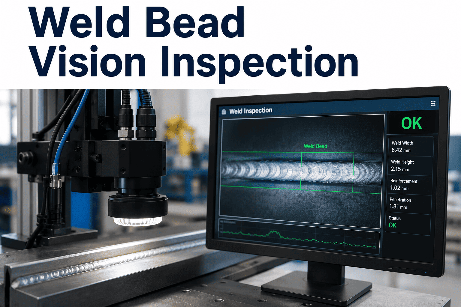
Measures bead width, height, reinforcement, and toe angle against the qualified weld geometry to catch dimensional deviation beyond visual defects.
Manual Inspection vs. AI Vision — Mapped to Acceptance Standards
| Factor | Manual Visual Inspection | AI Vision Inspection |
|---|---|---|
| Coverage | Sampled welds per shift | Every weld, every unit |
| Subsurface defects | Not detectable visually | Thermal signature correlation |
| Standard alignment | Inspector judgment | Thresholds mapped to AWS D1.1 / ISO 5817 |
| Documentation | Checklist or none | Image evidence per weld, logged automatically |
| Consistency | Varies by fatigue, shift, lighting | Identical standard applied every weld |
Rolling Out Weld Vision Inspection Station by Station
Weld inspection deployments succeed when they start where defects are most costly and expand from there. Most plants begin with structural body-in-white joints, where a missed defect carries the highest safety and warranty risk, then extend coverage to cosmetic and secondary welds once the model library and threshold tuning are validated against real production data.
Site Survey & Camera Placement
Lighting and camera angles are designed around the specific weld type and joint geometry, since low-angle directional lighting suits crack detection while diffuse lighting suits porosity.
Model Training on Real Defects
Pre-trained models are fine-tuned against your specific materials, welding parameters, and observed defect modes for higher accuracy than a generic library alone.
PLC Integration
Pass/fail decisions connect directly to the weld cell controller, enabling automatic rework routing before the body advances to the next station.
Closed-Loop Feedback
Defect trend data feeds back into welding parameter adjustment, helping prevent recurring defects rather than simply catching them after the fact.
Results From Structured Weld Vision Deployments
Across porosity, undercut, cracks, incomplete fusion, and spatter when models are tuned to production defect data.
Reduction in defects that reach downstream stations or field service after full inline weld vision coverage.
Of welds inspected at production speed, compared to sampled percentages under manual or X-ray audit programs.
Weld Bead Vision Inspection — Common Questions
Can AI vision catch subsurface porosity that visual inspection misses?
Yes, when the inspection pipeline fuses optical and thermal imaging rather than relying on optical cameras alone. Surface porosity is detectable through optical inspection, but subsurface porosity requires thermal imaging or correlative surface analysis, since the heat distribution pattern during and immediately after welding exposes fusion completeness and cooling rate anomalies that surface cameras cannot see. This multi-modal approach is why production deployments consistently outperform single-camera systems on defect types that used to require destructive testing to confirm.
How does the system decide what counts as a defect versus an acceptable variation?
Detection thresholds are programmed against recognized acceptance criteria such as AWS D1.1 or ISO 5817, so the same code-based limits that a certified welding inspector would apply are enforced automatically on every weld. Weld beads naturally vary in shape, color, and texture even when fully acceptable, and the model is trained specifically to distinguish that normal variation from genuine defects, reducing the false rejections that plague less carefully tuned vision systems.
Does this replace X-ray or ultrasonic testing entirely?
Not entirely. AI vision provides fast, continuous first-pass screening across every weld, catching the large majority of surface and near-surface defects at production speed. Certain subsurface conditions still benefit from non-destructive testing methods as a secondary confirmation step, particularly on safety-critical structural joints, so most plants run a layered inspection approach where vision handles volume and NDT handles targeted verification.
What happens when a weld is flagged as defective?
The system generates an automated severity classification and, depending on how the plant configures the workflow, either triggers an operator alert, an automatic part hold, or a direct work order for rework. Every flagged weld carries image and, where applicable, thermal evidence attached to the specific robot, station, and part number, giving the quality team a documented audit trail without needing to physically re-inspect the part.
How long does it take to deploy weld vision inspection on a new cell?
A single weld cell can typically be instrumented, calibrated, and validated within three to five weeks, including camera and lighting setup, model fine-tuning on production defect samples, and PLC integration for automated routing. Teams ready to scope a pilot can Book a Demo or reach the iFactory Support team for a deployment walkthrough.