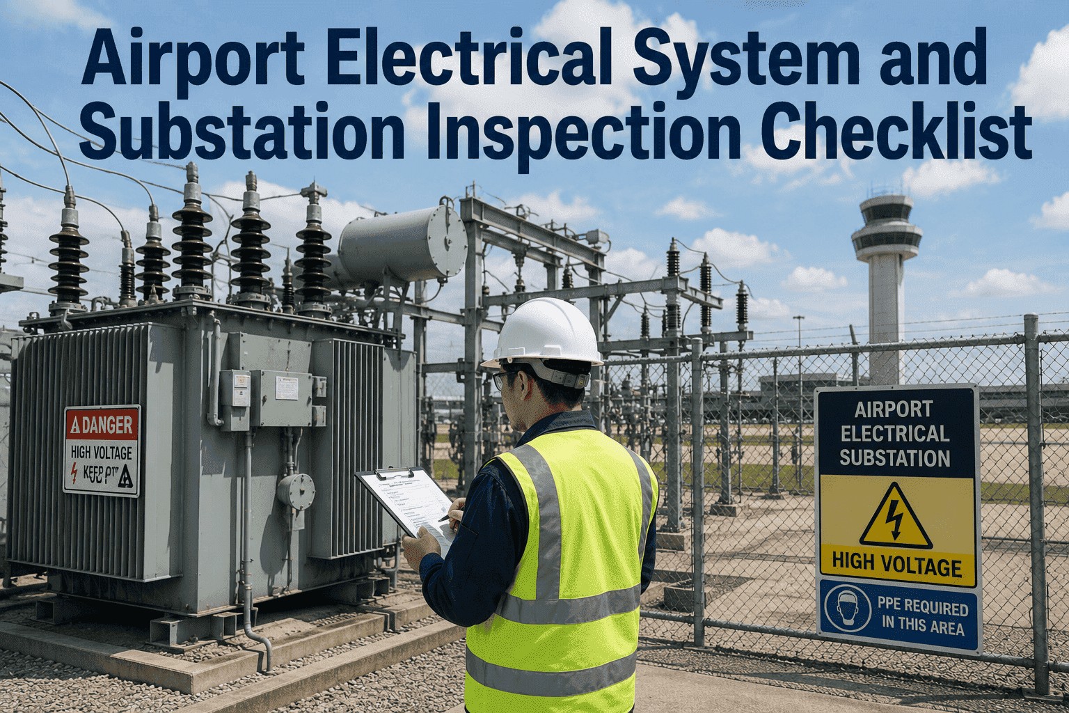
A single transformer failure at an airport substation doesn't just cut power to one terminal — it can simultaneously darken approach lighting, kill airfield CCR circuits, drop security cameras, and push emergency generators into simultaneous load that they were never stress-tested for together. Airport electrical infrastructure operates at the intersection of aviation safety, life safety, and regulatory compliance, yet the majority of inspection programmes still rely on calendar-based paper checklists rather than condition-driven analytics. This checklist gives airport electrical engineers, facilities managers, and compliance teams a structured, analytics-ready framework covering substations, transformers, switchgear, distribution panels, airfield series circuits, and grounding systems — every layer that stands between normal airport operations and an uncontrolled power event. Book a Demo to see how iFactory's Preventive Analytics platform drives condition-based inspection across your entire airport electrical asset base.
4.8x
higher cost for emergency switchgear failure response vs. a planned scheduled replacement
28%
longer transformer service life when oil analysis and thermographic checks are completed on schedule
6.6A
series circuit operating current — isolation transformer integrity is safety-critical at every maintenance visit
24/7
continuous load on airport HV systems demands condition-based scheduling, not annual calendar inspections
Airport Electrical Systems — Five Inspection Disciplines
Every layer connects to the one above and below it. A grounding failure becomes a switchgear hazard becomes a transformer fault becomes a terminal blackout.
The Hidden Cost of Deferred Electrical Inspection
Each system feeds risk into the next. Here is what the failure data shows about skipping scheduled checks.
Skipped Substation
Protection Gap
Uncalibrated protection relays fail to clear a fault within the defined time — downstream equipment sustains damage that a correct trip would have contained to a single breaker
Skipped Oil Analysis
Invisible Fault Growth
Internal arcing detected only at catastrophic failure — a transformer replacement costs 8–15x more than the oil treatment that would have extended service life by 10+ years
Skipped Switchgear
Arc Flash Escalation
Corroded contacts and undetected SF6 leaks combine with a switching operation to produce an arc flash event — a routine maintenance task becomes a fatality investigation
Skipped CCR Checks
Runway Lighting Failure
CCR output drift above ±3% produces non-compliant runway edge light intensity — an aircraft on approach in low visibility relies on certified brightness levels that no longer exist
Skipped Isolation Test
Series Circuit Electrocution Risk
Primary-to-secondary fault in an isolation transformer exposes the lamp socket to full series circuit voltage — standard re-lamping becomes a life-threatening task without isolation verification
Skipped Ground Test
Touch Voltage Hazard
Rising ground grid resistance goes undetected until a fault current event produces dangerous touch and step potentials — discovered during a post-incident inspection, not a scheduled one
Frequently Asked Questions
Inspection frequency depends on equipment type and voltage class. For airfield lighting systems, FAA AC 150/5340-26 requires monthly safety equipment inspections and regular functional testing of all circuits. MV switchgear and transformers typically require annual visual inspection, 3-yearly insulation resistance and contact resistance testing, and 5-yearly protection relay calibration. Transformer oil analysis should be conducted annually for units over 10 years old. Thermographic scanning is most useful on a quarterly basis under full load. Standby generator and ATS testing is typically monthly. Grounding system resistance testing is generally annual. Condition-based platforms like iFactory can replace fixed calendar scheduling with anomaly-triggered inspection orders, reducing unnecessary visits while catching early degradation that calendar schedules miss entirely.
Airfield lighting fixtures operate from the secondary side of isolation transformers fed by a series circuit carrying 6.6A at several thousand volts. Under normal conditions, the lamp operates at low secondary voltage. However, if a winding fault develops between the primary and secondary of the isolation transformer, the lamp socket becomes exposed to the full primary series circuit voltage — potentially several hundred volts — without any visible indication. Additionally, when a lamp is removed or fails on an energised circuit, the open secondary can produce up to 200V at the lamp connection point due to transformer resonance. FAA AC 150/5340-26C explicitly prohibits working on energised series circuits for this reason. Every visit to an airfield lighting fixture must begin with circuit de-energisation and induced voltage verification — this is not an optional precaution.
The Constant Current Regulator (CCR) must maintain output current within ±3% of rated value per FAA AC 150/5345-10. This tolerance exists because airfield lighting intensity is highly sensitive to current variation — a small change in output current produces a disproportionately large change in light output. If CCR current drifts above tolerance, runway edge lights and approach lights will not deliver their certified photometric performance. This matters most during reduced visibility operations: an aircraft flying an instrument approach in fog or at night is relying on lighting intensity levels that have been certified against specific current values. A CCR operating at degraded output without detection means the pilot sees less than the system was designed to provide. Operationally, CCR drift must be caught by calibration and monitoring — it produces no alarm and no visible symptom until lighting failure occurs.
Airport electrical maintenance sits at the intersection of several regulatory frameworks. FAA Advisory Circular AC 150/5340-26 (Maintenance of Airport Visual Aids) is the primary US standard for airfield lighting and series circuit electrical work. FAA AC 150/5345-10 governs CCR specification and testing. NFPA 70B provides recommended practice for electrical equipment maintenance including switchgear and transformers. IEEE C2 (National Electrical Safety Code) covers safety for high-voltage equipment. NFPA 70E governs arc flash safety and PPE requirements for electrical workers. IEEE C57.104 covers dissolved gas analysis interpretation for transformer oil. Internationally, IEC 60156 governs transformer oil dielectric testing. National civil aviation authorities and utility regulators apply additional local requirements. Maintaining traceable, timestamped, technician-attributed records for all inspections and test results is essential for CAA audit compliance — iFactory generates audit-ready documentation automatically for every work order and inspection event.
iFactory connects condition data from transformer oil analysis results, thermographic scans, CCR calibration records, switchgear test outputs, and grounding resistance measurements into a unified electrical asset record. Each transformer, switchgear panel, CCR, and distribution board becomes a tracked asset with a full condition history, maintenance record, and trend analysis. When sensor data or test results indicate an asset is approaching a defined threshold — transformer oil DGA showing rising gas levels, CCR output drift trends, or ground resistance increasing — iFactory generates a prioritised work order automatically and schedules it for a low-traffic maintenance window. The platform integrates with existing CMMS tools via REST API and typically reaches pilot go-live in 4–8 weeks. For airport electrical teams managing 24/7 critical infrastructure with limited maintenance windows, the shift from calendar-based to condition-based scheduling directly reduces both unnecessary inspections and undetected failures.
iFactory Preventive Analytics Platform
Stop Waiting for Electrical Failures to Announce Themselves. Start Predicting Them.
iFactory connects transformer condition data, CCR calibration records, switchgear test results, and ground resistance trends into a single asset health view — giving airport electrical teams the intelligence to act before a deferred inspection becomes a terminal outage. Trusted by infrastructure operators across the UK, EU, Middle East, and Asia-Pacific.
Pilot in 30 days. Full integration in one quarter.