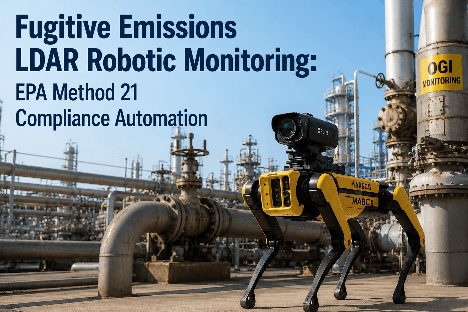
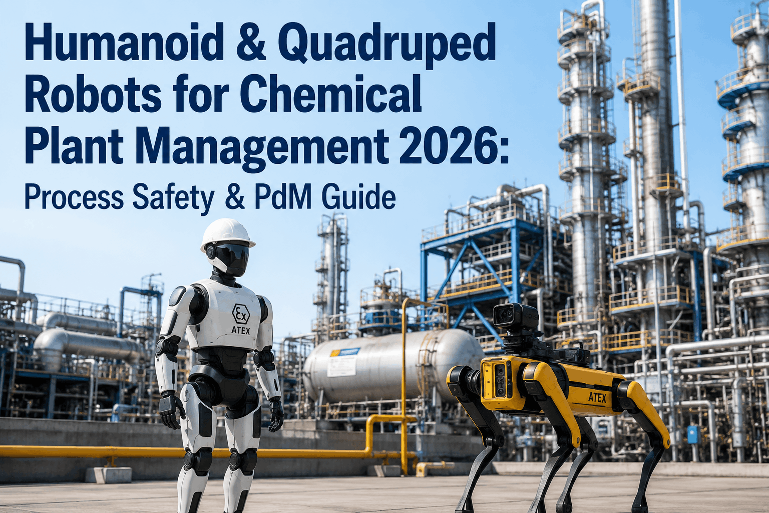
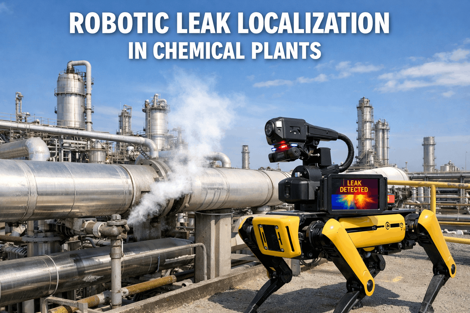
EPA Method 21 has governed fugitive emissions Leak Detection and Repair (LDAR) programs for 40+ years — but the regulation written in 1983 was never designed for the scale of fugitive emissions monitoring chemical plants face in 2026. Manual sniffer-based component-by-component inspections miss 2.4% of equipment, leak detection accuracy depends on technician timing, and the new EPA NSPS OOOOb/c with full Subpart W reporting by 2026 mandates continuous monitoring approaches that hand-held FID analyzers cannot deliver. The solution emerging across SOCMI refineries and chemical plants: ATEX-certified quadruped robots carrying OGI (Optical Gas Imaging) camera payloads, running 24/7 autonomous LDAR patrols at the 6 g/h sensitivity threshold validated by Concawe field studies for VOC mass emissions estimation. This guide breaks down robotic LDAR program design — Method 21 vs. AWP (Alternative Work Practice) compliance pathways, OGI camera selection, EPA 60.488 documentation requirements, and integration with EHS systems. Book an LDAR Robotic Monitoring Workshop to scope a compliant deployment for your facility.
40+ years
Since EPA Method 21 was promulgated — hasn't been substantially revised
6 g/h
OGI camera leak detection sensitivity for VOC mass estimation
2.4%
Of equipment historically monitored under Method 21 alone (Clearstone)
2026
Subpart W full implementation deadline — continuous monitoring expected
Why Manual LDAR Programs Are Failing in 2026
Traditional Method 21 programs were designed for a different era of chemical manufacturing. Three structural limitations now make manual LDAR insufficient — both for emissions reduction outcomes and for the regulatory documentation EPA expects. Read the broader chemical robot deployment context in our ATEX quadruped compliance guide.
F1
Snapshot Coverage Misses 50–80% of Leak Hours
Quarterly or semi-annual manual sweeps capture a single moment in time. A seal failing two days after the technician leaves stays undetected for up to 90 days until the next inspection cycle.
REAL-WORLD IMPACT
Princeton + Colorado State research found 5× more methane leaks than reported from offshore platforms — measurement frequency is the gap.
F2
DTM & UTM Components Stay Unmonitored
"Difficult to Monitor" (elevation) and "Unsafe to Monitor" (hazard zone) components require scaffolding, JLG lifts, or PPE-rated entry. Many facilities monitor these only annually, if at all.
REAL-WORLD IMPACT
Most large fugitive leaks occur at DTM/UTM components — exactly where Method 21 sniffer probes cannot easily reach.
F3
Subpart W Compliance Requires Continuous Data
Full Subpart W implementation by 2026 expects continuous emissions monitoring data. Hand-held FID analyzer surveys produce point-in-time snapshots — insufficient for the new reporting expectations.
REAL-WORLD IMPACT
Plants relying solely on Method 21 will struggle to meet 2026 NSPS OOOOb/c documentation requirements without supplementary continuous monitoring.
Method 21 Is Necessary. It Is No Longer Sufficient.
2026 LDAR programs need both Method 21 component validation and continuous robotic OGI surveillance to satisfy NSPS OOOOb/c expectations.
Method 21 vs. AWP vs. Continuous Robotic OGI — The 3 Compliance Pathways
EPA recognizes three valid pathways for LDAR compliance in 2026. Each has different cost profiles, detection sensitivity, and documentation requirements. Understanding which pathway fits your facility — and which combinations EPA accepts — is the foundation of any robotic LDAR deployment plan. Book a workshop to map the right pathway combination for your site.
PATHWAY A
Method 21 (Traditional)
Technology
Portable FID (Flame Ionization Detector) with probe
Codified
40 CFR Part 60 Appendix A-7 (1983)
Frequency
Quarterly / semi-annual per component type
Detection
ppm threshold-based (typically 500–10,000 ppm)
Pros
Established, universally accepted, component-level precision
Cons
Snapshot only, labor-intensive, DTM/UTM gaps
PATHWAY B
AWP / Smart LDAR (OGI)
Technology
Hand-held OGI cameras (FLIR GF320, MFE Mileva)
Codified
EPA Alternative Work Practice (Dec 2008) + Appendix K
Frequency
Same as Method 21, plus annual Method 21 backup
Detection
Visual identification of leak plumes; ~6 g/h sensitivity
Pros
Faster surveys, scans many components at once, safer
Cons
Still campaign-based, requires trained operators, weather-affected
PATHWAY C
Continuous Robotic OGI (2026)
Technology
ATEX-cert quadruped + OGI camera payload
Codified
AWP-equivalent under Appendix K + NSPS OOOOb/c
Frequency
24/7 autonomous patrols; minutes-scale leak detection
Detection
6 g/h sensitivity, AI-validated, continuous geo-tagged data
Pros
Zero exposure risk, full DTM/UTM coverage, Subpart W ready
Cons
CapEx investment, ATEX cert required, MOC review
EPA's expected 2026 norm: A hybrid combining Pathway C (continuous robotic OGI for surveillance) with periodic Method 21 component-level verification. Pathway C handles 90%+ of the detection workload; Method 21 provides regulatory backstop and component-level precision when leaks are confirmed.
OGI Camera Selection — What Matters for Robotic Mounting
The OGI camera is the most critical component of any robotic LDAR system. Not every OGI camera is suitable for quadruped mounting. The right camera matches gas type, weight envelope, ATEX certification, and EPA Appendix K compliance. Below is the technical comparison framework. Schedule a workshop to evaluate the right camera for your gas profile.
FLIR GF320
Spectral Band3.2–3.4 μm (MWIR)
DetectsMethane, VOCs, butane, propane
Sensitivity~6 g/h methane
Weight~2.5 kg (suitable for quadruped)
Appendix KYes — EPA-compliant
Industry standardMost widely deployed in SOCMI LDAR
MFE Mileva 33 OGI
Spectral Band3.2–3.5 μm (MWIR)
DetectsMethane + 30+ VOCs
Sensitivity<0.35 g/h methane (industry-leading)
Weight<1.5 kg (ideal for quadruped)
Appendix KYes — meets 40 CFR Part 60 Appendix K
Industry standardNewest generation, intrinsically safe
SeekOps Methane Detection
TechnologyTunable diode laser absorption (TDLAS)
DetectsMethane (primary), ethane
Sensitivity10 ppb (quantification at 20 g/h)
Weight~1 kg (ideal for drone or quadruped)
OutputQuantitative leak rate (g/h)
Best forTop-down emissions reconciliation
The Robotic LDAR System Architecture
A compliant robotic LDAR program is a layered system: ATEX-certified mobile platform carrying OGI camera payload, AI-powered leak detection and quantification, automated EPA-format documentation pipeline, and integration with your EHS and CMMS systems for repair workflow management. Read more in our chemical plant anomaly detection AI deep dive.
LAYER 1 — MOBILE PLATFORM
ATEX-Certified Quadruped Robot
ANYmal X (Cat 2G)
Sevnce Ex-Quadruped
Auto Route Planning
Geo-Tagged Patrols
24/7 autonomous patrols through Zone 1 and Zone 2 hazardous areas
LAYER 2 — AI LEAK DETECTION + QUANTIFICATION
Real-Time Plume Recognition + MABCS
Plume Recognition AI
Wind-Correlated Sizing
Leak Rate Estimation
False Positive Filter
MABCS (Mass-Above-Background Computational Sizing) converts plume video into g/h quantification
LAYER 3 — COMPLIANCE + WORKFLOW
EHS + CMMS Integration
EPA Subpart W Reports
CMMS Work Orders
Repair Timeline Tracking
Audit Trail Provenance
Auto-generated documentation aligned with EPA 60.488 and NSPS OOOOb/c
Robotic LDAR Is Not About Replacing Method 21. It's About Adding the Continuous Layer EPA Now Expects.
Subpart W reporting full implementation by 2026 requires continuous monitoring data that hand-held surveys cannot provide.
Book a workshop today to design your hybrid program.
EPA 60.488 Documentation — What Robotic LDAR Auto-Generates
EPA 60.488 specifies the recordkeeping requirements for fugitive emissions monitoring. Manual LDAR programs spend significant labor on this documentation; robotic systems generate it automatically as a byproduct of normal operation. Below is the documentation map — what's required, and what robotic systems produce out of the box.
D1
Component Inventory
EPA 60.488(a) — list of all valves, flanges, connectors, pumps in fugitive service
Robotic patrol routes built around geo-tagged component IDs; inventory updated continuously
D2
Monitoring Records
EPA 60.488(b) — date, component ID, leak/no-leak determination, measurement value
Every robotic patrol logs all component readings with timestamps, geo-coordinates, OGI video
D3
Leak Detection & Repair Logs
EPA 60.488(c) — repair work order, first attempt at repair, delayed repair justification
Auto-generated work orders in CMMS upon AI-confirmed leak; repair timeline tracked automatically
D4
Delayed Repair Documentation
EPA 60.488(d) — justification for leaks not repaired within 15 days
CMMS auto-flags delayed repairs; documentation prompts include process safety constraints
D5
Quarterly Reports
EPA 60.488(e) — summary of components monitored, leaks found, repairs completed
One-click quarterly report generation from continuous data stream
D6
Annual Performance Test
EPA 60.488(f) — annual demonstration of monitoring method performance
Built-in calibration cycles documented automatically with reference standards
The ROI Math — Robotic LDAR vs. Manual Programs
Robotic LDAR investments typically pay back within 12–18 months through three value streams: emissions credit / fine avoidance, lost product recovery, and labor reallocation. Below is the typical breakdown for a mid-sized SOCMI refinery LDAR program.
$2.5M+
Annual fine avoidance from improved leak detection compliance
$1.8M
Lost VOC product recovered annually via faster leak detection
60%
Reduction in LDAR labor hours through automation
VALUE STREAM BREAKDOWN
EMISSIONS CREDITS & FINE AVOIDANCE
EPA penalties for LDAR violations average $50K–$250K per incident. Robotic continuous monitoring reduces violation risk dramatically. Methane reduction also generates carbon credits in applicable jurisdictions.
LOST PRODUCT RECOVERY
Faster leak detection means less product loss. A single 10 g/h leak detected within hours instead of weeks recovers $40K+ annually per leak source. Multiply across hundreds of components.
LABOR REALLOCATION
LDAR technicians redirected from routine sniffer walks to higher-value tasks — leak diagnosis, repair execution, MOC reviews, and program optimization. Same workforce, dramatically more productive output.
SAFETY VALUE (HARDER TO MONETIZE)
Zero technician exposure to hazardous zones during patrols. Reduced JLG and scaffolding requirements for DTM components. Insurance premium reductions and liability exposure improvements.
FAQ: Robotic LDAR for EPA Method 21 Compliance
Common questions from EHS managers, plant compliance officers, and LDAR program leaders evaluating robotic OGI deployment. Question not covered? Reach our solutions team directly, or book an LDAR Workshop.
Does robotic OGI satisfy EPA Method 21 compliance on its own?
Not entirely on its own. EPA's Alternative Work Practice (AWP), promulgated in December 2008, allows OGI to be used in lieu of Method 21 for most components, but requires annual Method 21 monitoring of all accessible components as a backstop. Robotic OGI handles 90%+ of the routine surveillance workload under AWP; periodic Method 21 sniffer verification handles the regulatory backstop. The combined hybrid program is what most chemical plants are deploying in 2026.
What OGI sensitivity is required for EPA Appendix K compliance?
EPA's 40 CFR Part 60 Appendix K specifies camera performance requirements for OGI use in LDAR. The Concawe field study established 6 g/h methane sensitivity as the threshold most suitable for overall VOC mass emissions estimation at refinery sites. Modern cameras like the FLIR GF320 meet this; the MFE Mileva 33 OGI exceeds it significantly at <0.35 g/h. Camera selection must match your facility's gas profile, operating temperature ranges, and ATEX zone requirements.
How does MABCS quantification work for robotic OGI systems?
MABCS (Mass-Above-Background Computational Sizing) converts OGI plume video into quantitative leak rate estimates in g/h. The algorithm analyzes plume size, opacity, distance, and wind data to compute mass-above-background concentrations and derive leak rate. Modern systems pair OGI MABCS with TDLAS sensors (like SeekOps) for cross-validation. This produces the quantitative emissions data needed for Subpart W reporting — a step beyond traditional Method 21 ppm-threshold detection.
What about EPA NSPS OOOOb and OOOOc requirements?
OOOOb applies to oil and gas sites constructed, modified, or reconstructed after December 6, 2022. OOOOc applies to sites built on or before December 6, 2022. Both require LDAR with OGI per Appendix K, or alternatively use Method 21. OGI monitoring frequency ranges from quarterly to semi-annual depending on facility type. Robotic continuous OGI exceeds these frequency requirements by orders of magnitude, generating documentation aligned with both NSPS OOOOb/c and Subpart W reporting expectations.
Can robotic LDAR monitor SOCMI and refinery DTM/UTM components?
Yes — this is one of the strongest robotic LDAR value propositions. "Difficult to Monitor" (DTM) components at elevation and "Unsafe to Monitor" (UTM) components in hazardous zones are exactly where Method 21 sniffer probes struggle most. ATEX-certified quadrupeds with OGI payloads can traverse elevated platforms, walkways, and Zone 1/2 areas continuously, capturing leak data from components that human teams might inspect only once per year with significant safety risk and scaffolding cost.
How does robotic LDAR integrate with our existing EHS and CMMS systems?
Integration is standard through REST APIs and MQTT data streams. AI-confirmed leak detections auto-generate work orders in your CMMS (SAP PM, IBM Maximo, Oxmaint) with thermal video, geo-location, leak rate estimate, and component ID attached. Repair workflow tracks against EPA 60.488 timelines automatically. Quarterly and annual EPA-format reports generate from the same data store with one click — no manual report compilation. Audit trails include full data provenance from sensor through AI inference to compliance record.
What's the typical deployment timeline for a robotic LDAR program?
Standard deployment runs 12–16 weeks from contract signing to live operation. Weeks 1–3: hazard zone mapping, component inventory, route planning. Weeks 4–6: platform selection, OGI camera specification, ATEX certification matching. Weeks 7–9: pilot deployment in non-hazardous zones, AI model training on facility-specific gas patterns. Weeks 10–12: full hazardous zone deployment, CMMS integration. Weeks 13–16: parallel operation with existing LDAR program, validation, cutover to robotic-primary monitoring.
How quickly can we book an LDAR Robotic Monitoring Workshop?
Workshops are typically scheduled within 5–7 business days of request. The session is a
90-minute working call with your EHS, LDAR program, and operations teams — we map your current Method 21 / AWP program, fugitive emissions inventory, NSPS OOOOb/c applicability, and Subpart W readiness to a tailored robotic deployment plan. Output includes ATEX certification roadmap, OGI camera selection, EPA documentation pipeline architecture, and a 12-week deployment timeline.
Book your workshop now.
Build a 2026-Ready LDAR Program. Continuous Robotic OGI + Method 21 Verification.
EPA Subpart W full implementation, OOOOb/c expansion, and the structural limits of Method 21 make hybrid robotic LDAR the new standard. iFactory's LDAR Robotic Monitoring Workshop scopes your facility, gas profile, and existing program into a compliant deployment plan — ATEX-certified quadruped platform, EPA Appendix K-compliant OGI camera selection, automated EPA 60.488 documentation pipeline, and CMMS integration.
EPA Method 21 + AWP + Appendix K compliance
Subpart W and NSPS OOOOb/c ready
24/7 continuous monitoring at 6 g/h sensitivity
Full DTM/UTM component coverage
$2.5M+ annual fine avoidance and product recovery