A CIP system that looks identical on paper can perform completely differently on the plant floor depending on three design choices: spray ball coverage, flow velocity, and system pressure. Get any one of them wrong and a tank, pipeline, or heat exchanger will carry hidden soil into the next production run no matter how good the chemistry is. Engineers designing new CIP skids or retrofitting existing circuits need a repeatable sizing methodology, not guesswork borrowed from the last project, which is exactly what a Book a Demo session with iFactory's process engineering team is built to provide.
CIP SYSTEM DESIGN · SPRAY BALL · FLOW & PRESSURE ENGINEERING
Design CIP Systems That Clean Right the First Time
iFactory helps process engineers size spray devices, flow rates, and pump pressure correctly for tanks, pipelines, and heat exchangers before installation, not after a failed swab test.
The Three Design Variables That Determine Whether CIP Actually Works
Spray ball coverage determines whether every internal surface of a vessel is physically contacted by cleaning fluid. Flow velocity determines whether pipelines achieve the turbulent flow needed to lift soil off the pipe wall rather than just wetting it. Pressure determines whether the spray device delivers enough mechanical force to break down soil films without atomizing fluid into a mist that never reaches the surface at all. Design errors in any one of these three areas produce the same symptom: inconsistent swab results that seem to have no obvious cause.
1.5 m/s
minimum pipeline flow velocity typically required for effective turbulent cleaning
360°
spray coverage required from static or rotating devices for full tank wetting
2 to 4 bar
typical spray ball inlet pressure range for standard tank cleaning devices
30%
of CIP failures traced back to undersized pumps or misapplied spray devices
Spray Device Selection
Choosing the Right Spray Device for Each Vessel Type
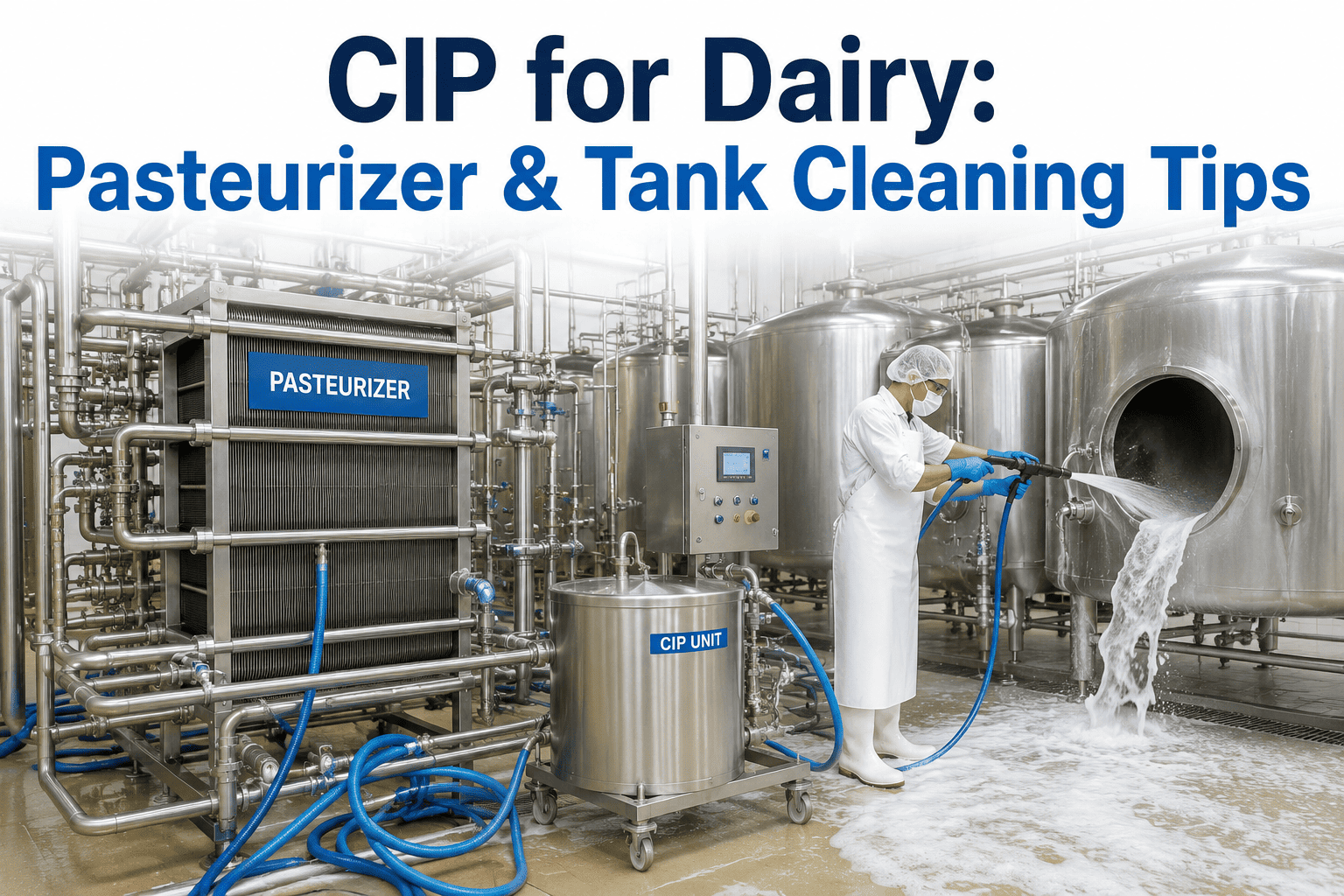
Not every tank needs a rotating spray head, and not every pipeline circuit needs the same return flow design. Matching the spray device to the vessel geometry, internal obstructions, and soil type is the single highest-leverage decision in CIP system design. Engineers who want a device selection matrix built for their specific vessel inventory can request one directly through Book a Demo.
Static Spray Ball
Low-Complexity Tanks
Fixed-pattern spray balls suit simple tanks with minimal internal obstructions and light to moderate soil loads. They are lower cost and easier to maintain, but coverage gaps around internal fittings or agitators need to be verified during riboflavin or UV-dye coverage testing.
Rotating Spray Head
Complex Geometry Vessels
Rotating devices deliver mechanical impact across a moving pattern, making them the right choice for tanks with agitators, baffles, or heavy, dried-on soil loads where a static pattern would leave shadowed zones behind internal obstructions.
Fixed Pipeline Velocity
Transfer and Process Lines
Pipelines rely entirely on flow velocity rather than spray impact, so pump sizing must guarantee turbulent flow across the full pipeline diameter, including any dead legs, which should be eliminated at the design stage wherever possible.
Plate Heat Exchanger Circuit
High Fouling Risk Equipment
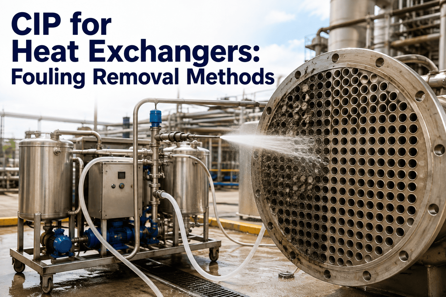
Heat exchangers require dedicated CIP circuits with reversible flow capability, since fouling can build unevenly across plate channels and reverse-flow cycles are often the only way to dislodge soil trapped in narrow channel gaps.
Sizing Reference
CIP Flow Rate and Pressure Sizing Benchmarks by Equipment Type
The following reference values reflect commonly applied CIP design benchmarks across food and beverage processing equipment. Actual values should always be validated against your specific soil load, pipe material, and vessel geometry using coverage testing before finalizing a design.
CIP Design Sizing Reference
CIP ENGINEERING · SKID DESIGN · PUMP SIZING
Get Your CIP Skid Sized Right Before You Install It
iFactory's process engineers review your vessel inventory, pipeline runs, and soil profile to build a flow, pressure, and spray device specification you can hand straight to your fabricator.
Design Mistakes
Four CIP System Design Mistakes That Cause Chronic Cleaning Failures
Most chronic CIP performance problems trace back to a small set of design mistakes made early in the project, long before the first swab test ever fails. Catching these during design review is far cheaper than retrofitting a return pump after installation.
01
Undersized Return Pump Capacity
Supply pumps are often sized correctly while return pumps are undersized, causing fluid to pool in the vessel base and reducing effective turbulent flow across the return leg of the circuit.
02
Dead Legs Left in Pipeline Design
Any pipe segment longer than a few pipe diameters that fluid does not actively flow through becomes a soil reservoir that no amount of CIP cycle time will ever adequately clean.
03
Spray Device Mismatched to Vessel Geometry
Installing a static spray ball in a tank with heavy internal obstructions leaves permanent shadow zones that only appear during formal coverage testing, well after installation is complete.
04
No Provision for Reverse Flow on Heat Exchangers
Single-direction CIP circuits on plate heat exchangers cannot dislodge soil trapped against plate ridges, leading to gradual fouling buildup that eventually shows up as reduced thermal performance.
Frequently Asked Questions
CIP System Design — Frequently Asked Questions
How do I know if my CIP pipeline flow rate is high enough?
Calculate the actual fluid velocity based on pump output and pipe internal diameter, then compare it against the turbulent flow threshold for your pipe size, generally around 1.5 to 2.1 meters per second for standard sanitary piping. iFactory's engineering review calculates this automatically from your existing pump curves and piping isometrics.
What is the difference between static and rotating spray balls?
Static spray balls deliver a fixed spray pattern through drilled holes and rely purely on chemical action and gravity flow, while rotating devices add mechanical impact through motion, making them better suited to vessels with dried-on soil, agitators, or complex internal geometry.
How often should spray coverage be verified after initial design?
Coverage should be re-verified with riboflavin or UV-dye testing whenever a vessel's internal configuration changes, such as adding an agitator or probe, and periodically as part of a broader CIP validation and requalification program to catch device wear or nozzle blockage.
Why does my heat exchanger keep fouling despite a working CIP cycle?
Single-direction flow through narrow plate channels often fails to dislodge soil trapped against plate ridges and gaskets. Adding a reverse-flow phase to the CIP cycle, along with verified flow velocity through every channel, typically resolves chronic fouling that a standard forward-only cycle cannot.
What pressure range is too high for CIP spray devices?
Excessive pressure can atomize cleaning fluid into fine mist that loses mechanical impact before reaching the surface, reducing cleaning effectiveness despite using more energy. Most spray ball applications perform best in the 2 to 4 bar range, with higher pressures reserved for specific high-fouling equipment types.
CIP SYSTEM DESIGN · FOOD GRADE ENGINEERING · 2026
Build a CIP System That Passes Coverage Testing on the First Try
iFactory's engineering team reviews your vessel and pipeline design and delivers a flow, pressure, and spray device specification tailored to your production environment.



-system-analytics-best-practices-for-food-and-beverage.png)