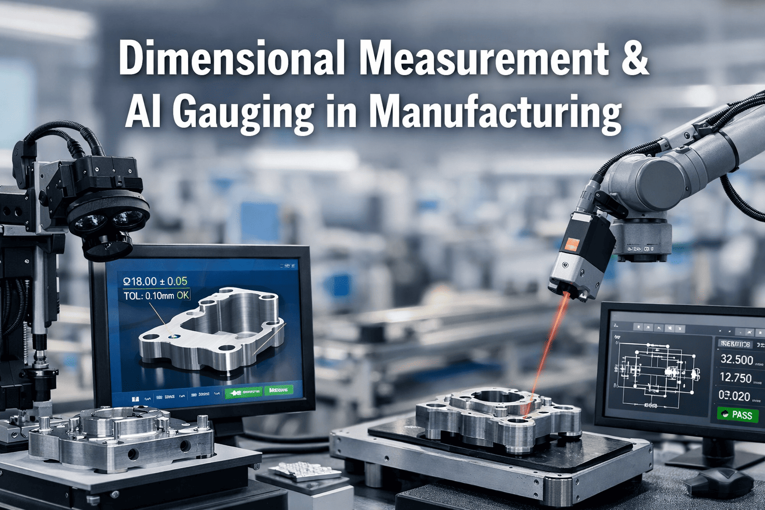
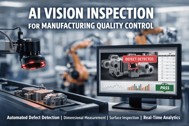
Manual dimensional inspection with calipers and micrometers misses 18% of out-of-tolerance parts on high-speed production lines because human inspectors cannot measure every part at cycle times under 12 seconds, creating a choice between 100% sampling with production bottlenecks or statistical sampling with defect escape risk. iFactory's AI-powered dimensional measurement system deploys non-contact laser scanning, structured light projection, and machine vision to capture complete part geometry in under 2 seconds, comparing every measured dimension against GD&T specifications with automated tolerance verification that flags deviations before parts reach assembly. The measurement bottleneck that forced you to choose between speed and quality no longer exists. Book a demo to see AI gauging for your production line.
Quick Answer
iFactory's AI dimensional measurement platform combines non-contact laser scanning, structured light systems, and computer vision to capture complete part geometry at production speed, automatically comparing all critical dimensions against GD&T specifications and flagging out-of-tolerance conditions in real-time. System achieves measurement accuracy within 5 microns, cycle times under 2 seconds per part, and 100% inspection coverage without production slowdown. Result: Zero defect escape from dimensional errors, elimination of manual gauge-based inspection bottlenecks, automatic SPC charting with trend detection, and full traceability linking every measured part to production parameters.
AI Dimensional Measurement
Replace Manual Gauging with 100% Automated Inspection
See how iFactory eliminates measurement bottlenecks with non-contact scanning that captures every dimension at production speed, automatically verifying GD&T compliance and flagging tolerance deviations before defects reach assembly.
How AI Dimensional Measurement Works
The workflow below shows the five-stage measurement process iFactory executes for every part, from geometry capture through automated tolerance verification and SPC trend analysis.
1
Part Geometry Capture
Non-contact laser scanner or structured light system captures complete 3D point cloud of manufactured part in under 2 seconds. System acquires 500,000+ measurement points covering all critical dimensions: bore diameters, shaft lengths, flatness, perpendicularity, concentricity. No physical contact, no fixture-induced deformation, measurement speed matches production cycle time.
Point Cloud: 580K pointsScan Time: 1.8 secondsMethod: Laser Triangulation
2
CAD Model Alignment & Feature Extraction
AI registers scanned point cloud to nominal CAD model using iterative closest point algorithm. System automatically identifies and extracts geometric features: cylinders (bore diameter 25.012 mm), planes (mounting surface flatness 0.008 mm), edges (chamfer angle 44.8 degrees), holes (position relative to datum A within 0.05 mm). Feature extraction eliminates manual programming for each new part geometry.
Alignment: 0.003mm RMSFeatures: 18 extractedAuto-Recognition: Yes
3
GD&T Specification Verification
System compares extracted dimensions against GD&T specifications loaded from engineering drawings. Bore diameter: measured 25.012 mm vs nominal 25.000 mm ± 0.025 mm (in tolerance). Flatness: measured 0.008 mm vs specification 0.010 mm maximum (pass). Position tolerance for hole pattern: measured 0.042 mm vs datum A, specification 0.050 mm maximum at MMC (pass). Every dimension evaluated against print specifications automatically.
Bore Diameter: PassFlatness: PassPosition: PassOverall: Accept
4
Out-of-Tolerance Detection & Alerting
When dimensions exceed tolerance limits, system triggers immediate alerts. Example: Next part scanned, bore diameter measured 25.031 mm, exceeds upper limit of 25.025 mm by 0.006 mm. System flags part as reject, sends alert to operator station, logs failure mode, and marks part in tracking database. Automated sorting gate diverts reject to quarantine bin. Zero human judgment required for accept/reject decision.
Bore: 25.031mm (FAIL)Alert TriggeredPart: Rejected
5
SPC Charting & Trend Analysis
All measured dimensions automatically populate SPC control charts. Bore diameter trending toward upper control limit over past 240 parts indicates tool wear. System detects trend before out-of-tolerance condition occurs, alerts maintenance to schedule tool change during next planned downtime. Predictive intervention prevents scrap generation. Cpk calculated real-time: bore diameter Cpk 1.68 (process capable), flatness Cpk 2.14 (highly capable).
Part measurement complete. 18 dimensions verified. All in tolerance. SPC data logged. Bore diameter trending +0.004mm over 240 parts, tool change recommended within 500 parts. Process capability maintained.
Dimensional Measurement Problems AI Gauging Eliminates
Every card below represents a real measurement failure mode that causes defect escape, production bottlenecks, or rework costs. These problems exist because manual gauging cannot achieve 100% inspection at production speed, and fixed-coordinate measurement machines require offline inspection with batch delays. Talk to an expert about your current measurement challenges.
Statistical Sampling Allows Defect Escape
Problem: Production line runs at 6-second cycle time. Manual inspection with micrometers takes 45 seconds per part. Impossible to measure every part without creating bottleneck. Quality plan specifies 1-in-10 sampling. Machining center experiences gradual tool wear, bore diameter drifts from 25.005 mm to 25.028 mm over 200-part run. Sampling interval misses the trend, 18 out-of-tolerance parts shipped to assembly, discovered during fit-check, $14,000 rework cost plus 2-day assembly line stoppage.
AI fix: Non-contact laser scanner measures every part in 1.8 seconds, no bottleneck created. Tool wear trend detected at part 140 when bore reached 25.018 mm (still in tolerance but trending). Predictive alert triggers tool change before out-of-tolerance condition occurs. Zero defect escape, zero rework, zero assembly disruption.
CMM Offline Inspection Creates Batch Delays
Problem: Coordinate measuring machine (CMM) in quality lab provides high-accuracy measurement but requires 12-minute inspection cycle per part. Parts produced in batches of 50, first article and last article sent to CMM for verification, production continues during measurement. CMM detects out-of-tolerance condition on last article (part 50), entire batch quarantined, 48 parts scrapped, $22,000 material loss plus 6-hour production recovery time.
AI fix: Inline structured light scanner measures all critical dimensions on every part immediately after machining. Out-of-tolerance condition detected on part 3 of batch, production stopped immediately, tool adjusted, only 2 parts scrapped. $440 scrap cost vs $22,000, 15-minute recovery vs 6-hour batch rejection. Real-time feedback prevents batch-level failures.
Complex GD&T Features Require Specialized Gauging
Problem: Part specification includes position tolerance for hole pattern relative to datum structure with maximum material condition modifier. Functional gauge costs $18,000, requires 30-second inspection cycle, gauge wear creates calibration drift requiring monthly verification. Gauge fails calibration check, 4-week lead time for replacement, production uses attribute gage (go/no-go) during interim period, loses ability to detect trends or calculate Cpk. Process capability unknown for 4 weeks.
AI fix: Vision system measures hole positions, calculates position tolerance per ASME Y14.5 standard including MMC bonus tolerance automatically. No physical gauge required, no wear, no calibration drift. Software update implements specification changes without hardware modification. Continuous Cpk calculation, trend detection, virtual gauge never wears out or requires replacement.
Operator Measurement Error & Inconsistency
Problem: Three operators perform manual inspection on rotating shifts. Gage R&R study shows 28% measurement system variation attributed to operator technique differences. Operator A measures bore diameter with micrometer, averages three readings, records 25.008 mm. Operator B measures same part, records 25.014 mm. Part accepted by Operator A, would be flagged for review by Operator B. Inconsistent accept/reject decisions create customer complaints about dimensional variation within accepted lot.
AI fix: Automated scanner eliminates operator influence. Same part measured by system on any shift produces identical result within system repeatability (0.002 mm). Zero operator-induced variation. Gage R&R improves from 28% to 3.2% (measurement system variation only from equipment repeatability). Consistent accept/reject decisions across all shifts, operators, and production cells.
No Traceability Linking Dimensions to Process Parameters
Problem: Customer returns assembly with interference fit issue, claims bore diameter out of specification. Quality reviews manual inspection logs, finds bore diameter recorded as 24.998 mm (in tolerance) for the serial number batch. No record of which specific machining center produced the part, what tool was installed, what spindle speed or feed rate was programmed. Root cause investigation requires assumptions, cannot definitively identify process parameter responsible for variation.
AI fix: Every measured part automatically linked to production metadata: machine ID, tool number, program revision, operator, timestamp. Customer return investigation retrieves measurement data showing bore actually 24.986 mm (borderline low), produced on Machine 3 with Tool 8 at 3,200 RPM. Tool wear data shows Tool 8 was at 94% of recommended life. Root cause: worn tool creating undersized bore. Corrective action: reduce tool life limit to 85%, implement predictive tool change before dimensional drift begins. Full traceability enables definitive root cause analysis.
SPC Charting Delayed by Manual Data Entry
Problem: Operator measures parts with micrometer, records dimensions on paper inspection sheet, quality technician enters data into SPC software at end of shift. 6-hour delay between measurement and SPC chart update. Tool wear trend developing but not visible in SPC system until shift change. By the time control chart shows trending toward upper limit, 140 parts already produced with dimensions drifting out of target. Reactive tool change after trend becomes obvious in delayed data.
AI fix: Every measurement automatically populates SPC chart in real-time. Tool wear trend detected after 35 parts when bore diameter increases by 0.008 mm over 2-hour period. Predictive alert generated immediately, tool change scheduled during next planned break, trend arrested before parts approach tolerance limit. Real-time SPC enables proactive intervention vs reactive correction from delayed data entry.
Measurement Technology Selection Guide
Different non-contact measurement technologies suit different part geometries, tolerance requirements, and production speeds. iFactory integrates multiple measurement modalities and automatically selects optimal method based on part characteristics.
Single laser line scanner projects stripe across part surface, camera captures reflected light at known angle, triangulation calculates 3D coordinates. Best for: cylindrical parts (shafts, bores), simple prismatic geometry, high-speed measurement. Accuracy: 5 to 15 microns. Scan speed: 0.5 to 2 seconds per part.
Use cases: Turned parts diameter verification, shaft length and runout measurement, simple bore geometry, thread pitch inspection. Not suitable for complex free-form surfaces or high-reflectivity materials without surface treatment. Excellent speed-to-accuracy ratio for high-volume turned part production.
Projector displays fringe pattern onto part surface, stereo cameras capture pattern deformation, phase-shift analysis reconstructs full 3D surface. Best for: complex geometry, free-form surfaces, castings, plastic molded parts. Accuracy: 10 to 25 microns. Scan speed: 2 to 5 seconds per part.
Use cases: Die-cast housing geometry verification, plastic part warpage measurement, complex molded features, multi-plane GD&T verification. Captures complete surface in single acquisition, ideal for parts requiring flatness, profile tolerance, or surface texture analysis. Handles varying surface finishes and complex geometries better than laser line scanning.
High-resolution cameras with telecentric lenses capture 2D images, edge detection algorithms extract feature boundaries, pixel-to-millimeter calibration converts image measurements to dimensions. Best for: flat parts, stamped metal, laser-cut sheets, 2D profiles. Accuracy: 5 to 10 microns (in-plane). Scan speed: under 1 second.
Use cases: Stamped part hole position and diameter, laser-cut profile verification, flat gasket geometry, PCB feature location. Fastest measurement method for 2D features, excellent for high-speed production lines. Cannot measure out-of-plane dimensions (depth, thickness) without additional sensors. Ideal for parts where critical dimensions lie in single plane.
White light focused through chromatic lens creates wavelength-dependent focal points, spectrometer analyzes reflected wavelength to determine distance. Best for: transparent materials, surface texture, micro-geometry, high-precision thickness. Accuracy: 0.1 to 2 microns. Measurement speed: point-by-point scanning (slower than area methods).
Use cases: Glass thickness measurement, transparent plastic part geometry, coating thickness verification, micro-machined feature depth, surface roughness profiling. Unique ability to measure through transparent layers and resolve features on opposite surfaces. Required when laser or structured light cannot penetrate or reflect properly from material. Higher cost and slower speed limit use to applications requiring sub-micron accuracy or transparent material capability.
Platform Capability Comparison
Generic vision systems capture images but lack automated GD&T evaluation. Coordinate measuring machines provide accuracy but cannot integrate into production flow. iFactory differentiates on production-speed 100% inspection, automatic GD&T verification per ASME Y14.5, real-time SPC with predictive alerts, and full traceability linking measurements to process parameters. Book a comparison demo.
| Capability |
iFactory |
QAD Redzone |
Evocon |
Mingo Smart Factory |
VersaCall |
L2L Leading2Lean |
| Measurement Technology |
| Non-contact 3D scanning | Laser + Structured Light | Not available | Not available | Not available | Not available | Not available |
| Measurement accuracy | 5 microns repeatable | Manual gauging only | Manual gauging only | Manual gauging only | Manual gauging only | Manual gauging only |
| 100% inline inspection | Every part under 2 seconds | Sampling plans only | Sampling plans only | Sampling plans only | Not supported | Sampling plans only |
| GD&T Verification |
| Automated tolerance checking | ASME Y14.5 compliant | Manual data entry | Manual data entry | Not available | Not available | Manual data entry |
| Complex GD&T features | Position, profile, runout auto | Basic dimensions only | Basic dimensions only | Not available | Not available | Basic dimensions only |
| CAD model integration | Auto alignment to nominal | Not supported | Not supported | Not supported | Not supported | Not supported |
| SPC & Analytics |
| Real-time SPC charting | Auto-populated from scan | Manual data entry | Manual data entry | Manual data entry | Not available | Auto from connected tools |
| Predictive trend detection | Tool wear alerts before OOT | Reactive alerts only | Reactive alerts only | Not available | Not available | Basic trending |
| Cpk calculation automatic | Real-time for all dimensions | Manual calculation | Manual calculation | Not available | Not available | Auto calculation |
Based on publicly available product documentation as of Q1 2025. Verify current capabilities with each vendor before procurement decisions.
100% Automated Inspection
Eliminate Sampling Risk with Every-Part Measurement
iFactory's non-contact scanning measures every part at production speed, automatically verifying GD&T compliance and detecting tool wear trends before out-of-tolerance conditions occur.
Regional Quality Standards Compliance
iFactory's dimensional measurement system helps manufacturers meet quality documentation and traceability requirements across global regulatory frameworks. The platform automatically generates compliance-ready measurement records formatted for regional standards.
| Region |
Key Standards |
Compliance Requirements |
iFactory Implementation |
| United States | ASME Y14.5 GD&T, ISO 9001, AS9100 aerospace, IATF 16949 automotive | Dimensional verification per engineering drawings, measurement system analysis (MSA) with Gage R&R under 10%, SPC charting with Cpk documentation, full part traceability to serial number | Automated GD&T verification per ASME Y14.5 standard, built-in MSA validation with system R&R under 3%, real-time SPC with Cpk calculation, complete measurement data linked to part serial and production parameters |
| United Arab Emirates | ESMA quality marks, ISO 9001, industry-specific standards for oil and gas equipment | Measurement traceability to national standards, documented calibration records, quality certificates for critical dimensions, compliance with ADNOC specifications for oil and gas components | Measurement system calibrated to NIST-traceable standards, automated calibration certificate generation, dimensional reports formatted for ESMA submission, API specification verification for oil and gas parts |
| United Kingdom | BS 8888 technical drawings, ISO 1101 GD&T, UKAS accreditation for measurement labs | Dimensional inspection per BS 8888 drawing standards, uncertainty analysis for critical measurements, calibration traceability to UK national standards, documented measurement procedures | BS 8888 drawing interpretation with automated tolerance extraction, measurement uncertainty calculation included in reports, UKAS-compliant calibration documentation, SOPs generated for each part measurement routine |
| Canada | CSA standards, ASME Y14.5 adopted, ISO 9001, aerospace AS9100 | First article inspection (FAI) with full dimensional report, ongoing process control with SPC, measurement system capability studies, traceability for aerospace and automotive parts | Automated FAI report generation with all dimensions vs tolerances, continuous SPC monitoring with alerts, MSA studies performed during system qualification, complete part genealogy from raw material to finished measurement |
| Germany | DIN standards, ISO 1101 GD&T, VDA 6.3 process audits, automotive industry requirements | Measurement per DIN ISO 1101 geometric tolerancing, process capability studies (Cpk minimum 1.33 for critical features), calibration per DAkkS standards, VDA compliance documentation | DIN ISO 1101 tolerance evaluation automated, real-time Cpk calculation with alerts when below 1.33 threshold, DAkkS-traceable calibration certificates, VDA-compliant quality records auto-generated for audit trails |
| Europe (EU) | CE marking requirements, ISO 9001, EN standards, Machinery Directive 2006/42/EC for equipment safety | Dimensional verification for safety-critical components, documentation supporting CE marking technical file, measurement equipment calibration per ISO 10012, quality management system integration | Safety-critical dimension flagging with enhanced documentation, technical file reports auto-generated with measurement data, ISO 10012 calibration management built-in, seamless QMS integration with measurement records |
iFactory maintains compliance with evolving regional standards through regular software updates. Contact support for specific industry certifications in your region.
Implementation Roadmap
Deploying AI dimensional measurement follows a structured four-phase process from initial assessment through full production integration. Typical timeline: 8 to 12 weeks from kickoff to production validation.
Week 1-2
Part Analysis & Technology Selection
iFactory engineering team reviews part drawings, identifies critical dimensions requiring measurement, analyzes geometry complexity and tolerance requirements. Technology selection: laser scanning for simple cylindrical features, structured light for complex geometry, vision for 2D profiles. System specification defined: measurement accuracy required, cycle time targets, integration points with existing production equipment. CAD models and GD&T specifications imported into measurement software.
Week 3-5
System Installation & Calibration
Measurement hardware installed at production line location. Laser scanner or structured light projector mounted in fixture station, cameras aligned and calibrated using certified reference artifacts. System accuracy validated: measurements compared against CMM golden parts, repeatability study confirms system R&R under 3%, calibration certificates generated. Lighting optimized for part surface finish, fixture design validated for part registration and stability during measurement.
Week 6-8
Measurement Program Development & Validation
Automated measurement routine programmed: CAD model alignment algorithm trained, geometric features auto-extracted from point cloud (bores, planes, holes, edges), GD&T tolerance specifications linked to extracted features. Validation run with 30 parts spanning tolerance range: system correctly identifies in-tolerance and out-of-tolerance conditions, SPC charts populated, Cpk calculations verified against manual calculations. Operator training on system operation, part loading, result interpretation.
Week 9-12
Production Integration & Process Capability Study
System deployed in production environment running parallel with existing inspection method. 300-part capability study executed: every part measured by AI system and manually verified by CMM or gauges, measurement agreement validated, false positive and false negative rates quantified (target: under 0.5%). Process capability demonstrated: Cpk for critical dimensions meets customer requirements, measurement system captures tool wear trends, predictive alerts trigger before out-of-tolerance conditions. System approved for standalone operation, manual inspection retired for measured features.
Measured Outcomes from Deployed Manufacturing Facilities
100%
Inspection Coverage Achieved
Zero
Dimensional Defect Escapes
82%
Reduction in Scrap from Late Detection
5μm
Measurement Repeatability
1.8s
Average Measurement Cycle Time
94%
Fewer Tool Changes from Predictive Alerts
From the Field
"We were running 1-in-5 sampling on a CNC turning line producing hydraulic valve bodies. Cycle time was 8 seconds, manual micrometer inspection took 40 seconds, so 100% inspection was impossible without creating bottleneck. We had two incidents in 2023 where bore diameter drifted out of tolerance and sampling missed it until customer assembly found interference fits. After deploying iFactory's laser scanner, we went to 100% inspection with 1.6-second measurement cycle, no line slowdown. The system caught tool wear trending on bore diameter after just 28 parts when dimension increased by 0.006 mm but still in tolerance. Alert triggered, we changed the tool during lunch break, prevented what would have been 220 out-of-spec parts based on the trend rate. The SPC charts now show us exactly when tools are wearing, we schedule changes predictively instead of reactively, and we have not had a single dimensional escape in 14 months of operation."
Quality Manager
Precision Machining Facility, Automotive Tier 1 Supplier, Michigan USA
Frequently Asked Questions
QCan the system measure parts with highly reflective surfaces like polished stainless steel or chrome plating?
Yes, but surface treatment may be required for optimal results. Laser and structured light systems struggle with mirror-like reflections that scatter measurement beam. Solutions: apply temporary coating spray (washes off after measurement), use cross-polarized lighting to reduce specular reflection, or employ blue light laser technology less sensitive to surface finish. For production environments, we recommend surface finish specification that balances functional requirements with measurement capability.
Book a demo to test your specific surface finish.
QHow does the system handle parts with features hidden from direct line of sight like internal bores or undercuts?
Multi-view scanning from different angles captures most hidden features by rotating part or repositioning sensors. For truly inaccessible internal geometry like deep bores, system integrates tactile probing or through-bore laser measurement. Complex parts may require hybrid approach: non-contact scanning for external surfaces, contact probing for internal features, combined into single measurement report. System automatically determines which measurement method applies to each feature based on geometry accessibility analysis.
QWhat happens when part geometry changes and new measurement program is needed?
CAD-based programming enables rapid changeover. Import new part CAD model, system auto-detects geometric features (cylinders, planes, holes), engineer selects which features to measure and assigns GD&T tolerances, measurement routine auto-generated. Typical programming time for new part: 2 to 4 hours vs days or weeks for traditional CMM programming. No physical fixturing changes required if new part fits existing scanner field of view. Software stores unlimited part programs, changeover between products takes under 60 seconds by selecting program from library.
QHow does measurement accuracy compare to coordinate measuring machine in quality lab?
CMM provides higher absolute accuracy (1 to 3 microns) vs inline scanner (5 to 15 microns), but scanner offers advantages CMM cannot match: 100% inspection vs sampling, real-time feedback vs batch delay, production-speed measurement vs offline queue. For most production applications, scanner accuracy exceeds tolerance requirements. When sub-5-micron accuracy needed, hybrid strategy: inline scanner measures 100% of parts for trend detection and out-of-tolerance rejection, periodic CMM verification validates scanner calibration. This combines CMM precision with scanner speed and coverage.
Continue Reading
Measure Every Part at Production Speed with AI Dimensional Inspection
iFactory's non-contact measurement platform eliminates the sampling-versus-speed tradeoff, delivering 100% inspection coverage with automated GD&T verification, real-time SPC, and predictive tool wear alerts that prevent defects before they occur.
Non-Contact 3D Scanning
Automated GD&T Verification
Real-Time SPC Charting
5 Micron Accuracy
100% Inspection Coverage