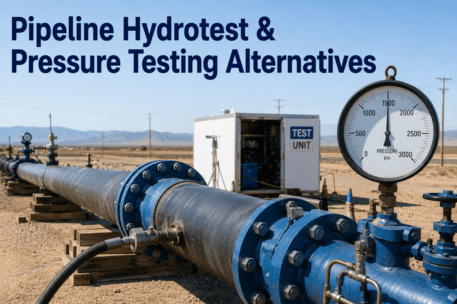
Hydrostatic pressure testing has been the accepted method for validating pipeline integrity for over five decades, establishing a track record that regulators, operators, and engineering standards all recognize as the baseline proof of fitness for service. The principle is straightforward — pressurize the pipeline with water to a specified level above maximum allowable operating pressure, hold the pressure for a defined duration, and if the pipe holds, it is deemed capable of safe operation. However, hydrotesting carries significant costs, operational disruptions, and environmental risks that become increasingly difficult to justify as in-line inspection technology and engineering critical assessment methods mature. A single hydrotest on a 100-mile gas transmission pipeline can cost $1.5 million to $4 million when water sourcing, treatment, filling, testing, dewatering, drying, and disposal are all included, plus the revenue loss from a multi-week shutdown. iFactory AI helps operators evaluate whether hydrotesting, ILI, or ECA is the right integrity validation approach for each segment. Book a demo.
The Pressure Testing Spectrum: From Commissioning to Revalidation
Pipeline pressure testing exists on a spectrum defined by the test pressure level relative to MAOP, the purpose of the test, and the regulatory context in which it is performed. Understanding this spectrum is essential for selecting the correct test level and for evaluating whether a lower-pressure alternative can provide equivalent integrity assurance. The following visual maps the five primary pressure test levels from standard operating pressure through new-construction commissioning tests, showing the pressure multiplier, typical hold duration, and the primary integrity question each level answers.
Method Comparison Scorecard: Hydrotest vs ILI vs ECA
Each of the three primary integrity validation methods — hydrostatic testing, in-line inspection, and engineering critical assessment — excels in different dimensions and falls short in others. The following scorecard evaluates each method across six critical performance dimensions using a consistent scale, enabling operators to compare methods objectively against the specific requirements of their pipeline system, regulatory jurisdiction, and risk tolerance.
Hydrotest Pressure Calculation: Building the Test Pressure Step by Step
The test pressure for a hydrostatic revalidation test is not simply 1.25 times the current MAOP. The calculation must account for the pipeline location class, the specified minimum yield strength of the pipe steel, the temperature derating factor at test conditions versus operating conditions, and any elevation differences between the test section high point and low point. The following framework shows how the test pressure is built from the base MAOP through each adjustment factor to arrive at the final test pressure that satisfies both the code minimum and the pipe material limits.
ILI as a Hydrotest Alternative: What ILI Can and Cannot Replace
In-line inspection has advanced to the point where many regulators and operators now consider ILI-based integrity management as equivalent to or better than periodic hydrotesting for certain pipeline applications. However, the equivalence is not universal — ILI replaces the flaw characterization function of hydrotesting but does not replace the flaw removal function. Understanding this distinction is critical for making sound integrity decisions and for building regulatory cases that justify ILI-based revalidation in jurisdictions where hydrotesting remains the default requirement.
Engineering Critical Assessment: Fracture Mechanics Without Pressurization
Engineering critical assessment applies fracture mechanics principles to determine whether a known flaw is safe to remain in service at a specified operating condition. ECA does not require any pressurization beyond normal operations — it is a purely analytical method that takes flaw dimensions from ILI data or direct examination, material properties from mill test reports or in-situ testing, and stress analysis from operating conditions to calculate the critical flaw size and the remaining life of the assessed flaw. ECA is the most cost-effective integrity validation method for individual anomalies, but its acceptance as a standalone revalidation alternative varies significantly by regulator.
Cost and Outcome Comparison: What Operators Actually Pay
The true cost of each integrity validation method extends well beyond the direct execution cost. Hydrotesting includes water management, pipeline downtime, and environmental compliance costs that are often underestimated in initial budgeting. ILI includes tool mobilization, temporary facilities, and the subsequent repair program that ILI findings trigger. ECA includes engineering analysis labor, material testing costs, and the regulatory approval process. The following comparison quantifies these costs for a representative 100-mile, 24-inch gas transmission pipeline to enable operators to make informed decisions based on total cost of ownership rather than headline execution cost.
Regulatory Acceptance Matrix: Where Each Method Is Recognized
Regulatory acceptance of alternative integrity validation methods varies significantly across jurisdictions and is evolving as ILI technology and ECA methodologies mature. The following matrix summarizes the current regulatory position in the three primary North American pipeline regulatory frameworks, based on published guidance, approved variances, and established precedent from operator submissions. Operators considering ILI or ECA as hydrotest alternatives should verify current acceptance status with their specific regulatory authority before proceeding, as guidance documents are updated periodically.
| Validation Method | PHMSA (U.S. Federal) | TC Energy (Canada) | State Regulatory Programs |
|---|---|---|---|
| Hydrostatic Test at 1.25x MAOP | Universally accepted as baseline revalidation method per 49 CFR 192 | Accepted per CSA Z662 Clause 10; standard requirement for revalidation | Accepted in all state programs; some states require additional notification |
| Spike Hydrotest (1.1–1.25x, short hold) | Accepted for crack mitigation per IMP guidance; not standalone revalidation | Accepted as crack mitigation measure; supplementary to baseline ILI program | Varies by state; generally accepted with engineering justification |
| ILI-Based Revalidation (MFL/UT) | Accepted per 49 CFR 192 Subpart O as alternative to pressure testing with regulatory approval | Accepted as primary integrity management method per CSA Z662 with demonstrated tool performance | Accepted in most states with IMP variance application; some states require hydrotest backup |
| ILI-Based Revalidation (Crack Detection) | Accepted on case-by-case basis; PHMSA guidance evolving for EMAT/UT crack tools | Accepted for SCC management programs with proven tool performance validation | Limited precedent; generally requires supporting hydrotest or ECA for regulatory comfort |
| Engineering Critical Assessment | Accepted for individual anomaly assessment per API 579; not yet accepted as standalone revalidation | Accepted per CSA Z662 Annex O for specific flaw assessment; growing acceptance for program-level use | Generally limited to supporting role for repair decisions; not primary revalidation method |
Expert Perspective: The Hydrotest Decision Should Be Data-Driven, Not Habitual
I have been involved in over 60 hydrostatic tests on gas transmission pipelines ranging from 6-inch to 42-inch diameter across the U.S. and Canada, and I have managed the transition from hydrotest-based revalidation to ILI-based integrity management for three separate pipeline systems totaling over 2,000 miles. The most common mistake I see is operators hydrotesting pipelines out of habit rather than analysis — running a test because the regulatory clock says it is time, not because the data indicates hydrotesting is the right tool for the risk profile of that specific pipeline. I have seen a 36-inch pipeline hydrotested at a cost of $3.8 million that had no history of manufacturing defects, no evidence of time-dependent cracking, and a comprehensive ILI dataset showing no anomalies within 50% of the critical flaw size at 1.25x MAOP. The hydrotest produced zero failures, confirmed what the ILI data already indicated, and consumed $3.8 million that could have funded ILI runs on five additional pipeline segments. Conversely, I have seen operators attempt to avoid hydrotesting on a 20-inch pipeline with a known history of ERW seam failures from the 1960s, where the ILI tool performance specification for longitudinal seam defects was insufficient to provide equivalent assurance. That pipeline needed a hydrotest, and the attempt to substitute ILI was a risk-based decision that the regulator rightfully challenged. The right answer is always specific to the pipeline: its manufacturing history, its operating conditions, its threat profile, and the detection capability of the available ILI technology for the defect types that matter on that line. Book a demo to see how iFactory builds this pipeline-specific analysis.
Frequently Asked Questions
ILI can replace hydrostatic testing for revalidation in many, but not all, circumstances. The replacement is justified when the ILI tool's detection capability for the relevant defect types meets or exceeds the effective flaw removal capability of the hydrotest at the specified test pressure. For corrosion metal loss, modern MFL tools with 80-90% probability of detection for anomalies exceeding 20% wall thickness can provide equivalent or better integrity assurance than a 1.25x MAOP hydrotest, because the hydrotest only removes flaws larger than the critical size at test pressure while the ILI tool characterizes all flaws above its detection threshold. However, for manufacturing defects in older ERW pipe, hook cracks in submerged arc welds, or stress corrosion cracking where ILI detection probability is lower, hydrotesting may still provide superior assurance because it does not rely on detection — it relies on the physics of fracture at the test pressure. Book a demo to see how iFactory evaluates this equivalency for each pipeline segment.
A spike hydrotest involves pressurizing the pipeline to 1.1 to 1.4 times MAOP for a short duration — typically 1 to 2 hours rather than the standard 8-hour hold — with the specific objective of causing subcritical cracks to grow to a detectable size or to fail cracks that are near their critical size at operating pressure. The spike test is not a standalone revalidation method; it is a crack mitigation technique used in conjunction with ILI as part of a comprehensive SCC management program. The theory is that the brief overpressure causes crack tips to extend through the ligament between crack and the pipe outer surface, making the cracks detectable by subsequent ILI or causing them to fail and leak during the spike, which identifies the location for repair. Spike testing has been used extensively on Canadian pipelines with near-neutral pH SCC, with documented effectiveness in reducing the population of subcritical cracks. iFactory tracks spike test parameters and post-spike ILI results to quantify crack mitigation effectiveness. Contact support for spike test analysis workflows.
A failure during hydrostatic testing means a flaw existed in the pipeline that was larger than the critical flaw size at the test pressure. The failure typically produces a leak or rupture at the flaw location, releasing the test water. The immediate consequences include emergency response to secure the site, depressurize the test section, and assess the failure location. The failure is then investigated through metallurgical analysis of the failed section to determine the defect type, origin, and size — was it corrosion, cracking, manufacturing defect, or mechanical damage? The repair involves cutting out the failed section, replacing it with a new pipe joint, and re-testing the repaired section. The broader consequences include a regulatory reportable incident filing, potential additional regulatory scrutiny of the entire pipeline system, extended downtime while the failure investigation and repair are completed, and a reassessment of whether other sections of the pipeline may contain similar defects. While a hydrotest failure is disruptive and costly in the short term, it is fundamentally a success in integrity terms — the test identified and removed a flaw that would have failed at operating pressure, preventing a potentially far more consequential in-service failure.
Pneumatic testing uses compressed gas (typically air or nitrogen) instead of water as the test medium. The stored energy in compressed gas at pipeline pressures is approximately 200 times greater than the stored energy in water at the same pressure, which means a pneumatic test failure releases dramatically more energy and produces a much more violent failure mode than a hydrotest failure. For this reason, ASME B31.4 and B31.8 impose strict limitations on pneumatic testing: the test pressure is limited to 1.1 times MAOP (versus 1.25x for hydrotest), the pipe must be proven to have adequate toughness through material testing, and the pipeline must be located in areas where the risk to the public from a pneumatic failure is acceptable. Pneumatic testing is used primarily where water cannot be used — in arid regions where water is unavailable, in pipelines that cannot be adequately dried after hydrotesting, or in situations where water disposal would create environmental problems. The safety restrictions and lower test pressure make pneumatic testing a last resort rather than a preferred alternative to hydrotesting.
iFactory builds a segment-specific integrity validation recommendation by evaluating six factors for each pipeline segment: manufacturing history and known defect susceptibility, current ILI dataset quality and tool performance for the relevant defect types, operating conditions including pressure cycling and temperature profile, regulatory jurisdiction and current acceptance of alternative methods, cost comparison including direct execution cost and indirect costs like downtime, and the consequence of failure at each segment based on location class and population density. The output is a ranked recommendation for each segment — hydrotest recommended, ILI-based revalidation recommended with conditions, or ECA recommended for specific anomaly management — with a quantitative justification that can be submitted to regulators as supporting documentation for alternative revalidation approaches. The model is updated as new ILI data, CP survey results, or operating condition changes become available, ensuring the recommendation reflects current pipeline condition rather than historical assumptions. Book a demo to see the decision framework in action.