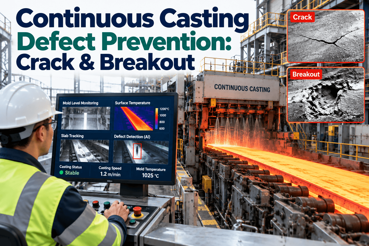
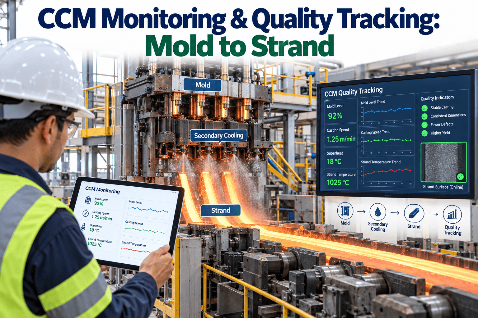
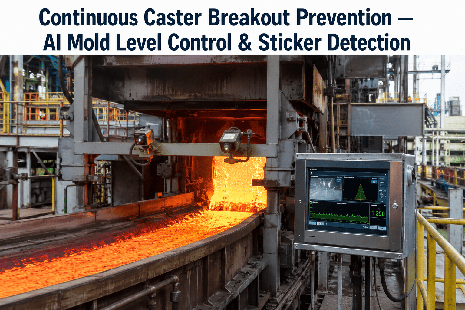
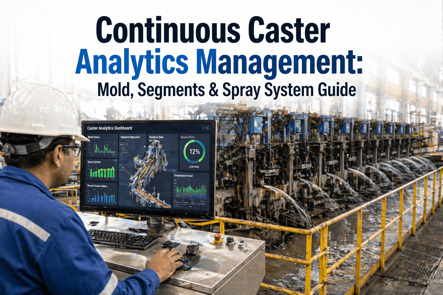
A breakout on a continuous casting machine is the most consequential failure event in a steel melt shop — molten steel at 1,550°C escaping through a thinned or perforated mold shell below the copper plate, flowing into the strand guide, flooding the secondary cooling zone, and in severe cases reaching electrical equipment and cooling water systems. A single breakout event costs $1.8 to $4.5 million in direct damagecleanup and production loss, typically requiring 48 to 96 hours of full caster shutdown. For a caster producing 1,500,000 to 3,000,000 tons per year, that production gap compounds through the downstream rolling and finishing schedule for weeks. What makes breakouts particularly damaging is that they are almost never unannounced. The mold thermocouple network records the asymmetric heat transfer pattern that indicates a developing shell thin spot 4 to 12 minutes before the breakout event. The mold friction signal shows the stick-slip pattern that precedes a sticking-type breakout 2 to 5 minutes before strand arrest. The problem is not absent data. It is the absence of a real-time analytics system that applies the right detection models to those signals with the speed and specificity required to trigger a controlled strand slowdown before the failure threshold is crossed. iFactory's continuous casting analytics and breakout prevention platform applies exactly those models — monitoring mold heat transfer patterns, strand shell behavior, segment alignment, spray cooling performance, and tundish condition simultaneously to prevent breakouts, optimize slab quality, and extend segment and mold equipment life. Casters running iFactory's casting analytics platform report 94% reduction in breakout events, 28% reduction in slab internal defect rates, and average annual value of $2.1 million per strand from combined breakout avoidance and quality improvement.
Why Continuous Casting Requires a Multi-Signal Analytics Platform — Not Just Mold Alarms
The failure modes that cause breakouts and slab quality defects on a continuous caster do not originate from a single abnormal reading on a single sensor. They develop as compound conditions across multiple systems — mold heat transfer, oscillation behavior, secondary cooling, segment alignment, and tundish temperature — that individually appear manageable but converge to produce catastrophic or quality-critical outcomes. A mold thermocouple showing 15°C above baseline is not, by itself, a breakout alarm. The same reading combined with asymmetric heat transfer across the narrow face, a simultaneous friction signal increase, and a tundish temperature 25°C above target creates a compound condition that requires immediate strand slowdown. That compound condition is invisible to any single-parameter alarm system. It requires an analytics platform that monitors all five systems simultaneously, applies cascade failure detection logic trained on caster-specific failure patterns, and delivers the right response to the operator with enough lead time to act.
The business case for continuous casting analytics is built on the cost differential between a prevented breakout and an executed one — and between a slab quality issue detected at the caster and one detected at the rolling mill or at the customer. For facilities evaluating the investment, Book a Demo to see how iFactory's caster analytics would perform on your specific machine configuration and product mix.
Mold Heat Transfer and Shell Formation
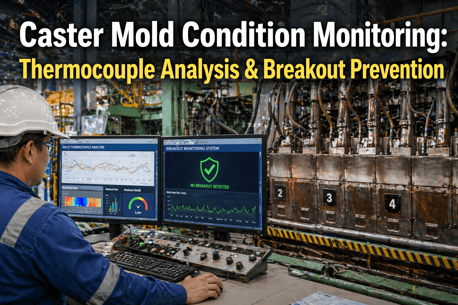
The mold thermocouple pattern is the primary breakout detection signal — asymmetric heat transfer indicating a thin shell sector, heat flux drop indicating powder entrapment, and symmetric low-heat-flux areas indicating shell bridging. Each pattern has a distinct thermocouple signature detectable 4 to 12 minutes before the breakout threshold.
Strand Friction and Oscillation Monitoring
Mold oscillation friction signals carry the earliest warning of sticking-type breakouts — the stick-slip pattern that precedes strand arrest and mold shell tearing. Oscillation stroke deviation and mold level hunting are secondary signals that confirm developing abnormal friction conditions before the primary thermocouple pattern deteriorates.
Secondary Cooling and Segment Alignment
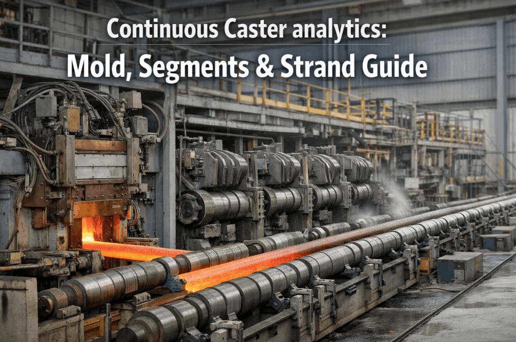
Secondary cooling spray headers, segment roll gaps, and segment hydraulic pressure systems determine strand shell solidification profile and surface quality. Misaligned segments, blocked spray nozzles, and incorrect roll gap settings produce internal cracking, longitudinal surface cracks, and rhomboidity defects that reach the rolling mill as quality rejections without any mold-level detection.
Tundish and Casting Powder Management
Tundish temperature, steel cleanliness, and mold powder consumption rate directly affect shell formation quality and breakout probability. A tundish temperature 30°C above target increases breakout probability by more than 60%. Mold powder consumption below target indicates insufficient lubrication — the leading cause of sticking-type breakout events.
Breakout Prevention: The Real-Time Detection Models That Stop Breakouts Before They Happen
iFactory's breakout prevention system applies four simultaneous detection models — each targeting a distinct breakout mechanism — to the continuous data stream from the mold thermocouple array, friction measurement system, mold level sensor, and oscillation encoder. When any model's output exceeds the configured risk threshold, the system issues a graduated response: speed reduction advisory at the first threshold, automatic speed reduction at the second, and full strand slowdown at the critical threshold — all before the breakout condition reaches the point of no recovery. Book a Demo to see the breakout detection models applied to your caster's mold configuration.
The asymmetric heat transfer model monitors the thermocouple matrix in the mold copper plate continuously, applying a pattern recognition algorithm that identifies the characteristic heat flux distribution signature of a developing thin shell sector. A true breakout-precursor pattern shows a local heat flux reduction in one thermocouple zone spreading downward in subsequent measurement cycles as the thin shell moves below the thermocouple row — distinguishable from normal casting disturbances by the propagation velocity and spatial pattern. iFactory's model applies a cascade detection logic: single-zone anomalies generate an alert; multi-zone propagating anomalies below 4 minutes before the model-predicted breakout time trigger automatic speed reduction via OPC-UA write-back to the caster speed control. Detection lead time: 4 to 12 minutes before the breakout event at casting speeds above 1.0 m/min.
Sticking-type breakouts are caused by shell adhesion to the mold copper plate at the meniscus — the strand shell bonds to the mold during the negative strip phase of oscillation, then tears when the positive strip phase cannot overcome the adhesion force. The pre-failure signature is a characteristic stick-slip pattern in the mold friction signal: a stepwise increase in friction force during the negative strip phase followed by an asymmetric recovery in positive strip. This pattern appears 2 to 5 minutes before strand arrest in validated sticking breakout events. iFactory's sticking detection model monitors the oscillation friction index (calculated from mold oscillation drive force signals) at each oscillation cycle and triggers a speed reduction recommendation when the stick-slip pattern meets the configured detection criteria — 3 to 8 oscillation cycles before the adhesion becomes irreversible.
Mold level disturbances — hunting caused by SEN clogging or stopper rod response degradation, level drops from tundish temperature excursions, or level spikes from argon injection flow surges — directly affect shell formation uniformity and create conditions for longitudinal cracking, deep oscillation marks, and powder entrapment that precede breakouts. iFactory's level instability model applies spectral analysis to the mold level signal, distinguishing the frequency characteristics of normal level control response from the irregular low-frequency oscillation patterns that indicate SEN partial blockage or stopper control degradation. Alert-to-action lead time: 3 to 8 minutes before level deviation reaches the emergency threshold defined in the caster's breakout response procedure.
The compound risk index integrates outputs from all three individual detection models with tundish temperature deviation, mold powder consumption rate (calculated from level changes between powder additions), and secondary cooling spray total flow deviation into a single Breakout Risk Score (BRS) that is updated every 10 seconds. Each contributing parameter is weighted by its empirically validated contribution to breakout probability for the current product grade, casting speed, and steel composition. A BRS above 65 triggers an operator advisory; above 80 triggers automatic speed reduction; above 92 triggers the full emergency slowdown protocol. This compound approach reduces both false positives — which cause unnecessary speed reductions that cost productivity — and missed detections, which are the events that end in actual breakout incidents.
| Breakout Type | Primary Signal | Detection Pattern | BRS Contribution | Automatic Response | Lead Time |
|---|---|---|---|---|---|
| Shell Thinning (Thermal) | Mold thermocouple pattern — asymmetric flux reduction | Downward propagating low-flux zone across TC rows | 0–45 points | Speed reduction at BRS 80 | 4–12 min |
| Sticking Breakout | Mold friction — stick-slip oscillation pattern | Stepwise friction rise in negative strip phase | 0–40 points | Speed reduction at BRS 80 | 2–5 min |
| Level Disturbance Breakout | Mold level signal — irregular low-frequency hunting | Spectral anomaly at 0.02–0.08 Hz band | 0–25 points | SEN/stopper advisory at BRS 65 | 3–8 min |
| Powder Entrapment Breakout | Mold powder consumption + level heat flux pattern | Below-target consumption + local heat flux anomaly | 0–30 points | Speed reduction + powder addition prompt | 5–15 min |
| High Tundish Temperature Breakout | Tundish thermocouple — temperature above target | Temperature >target+25°C for >3 minutes | 0–20 points | Speed reduction advisory at BRS 65 | Continuous |
Slab Quality Analytics: Detecting Internal and Surface Defects at the Caster Before They Reach the Rolling Mill
Breakout prevention addresses catastrophic failure. Slab quality analytics addresses the far more frequent category of defects — internal cracks, longitudinal surface cracks, rhomboidity, and transverse corner cracks — that are generated by equipment and process conditions in the caster but not detected until downstream. Each of these defect categories has a specific origin in the caster's equipment and process condition, and each is detectable from the analytics data stream before the slab leaves the strand guide. The defect attribution table below maps the five primary slab quality defect categories to their caster-level causes, the monitoring parameters that detect them, and the intervention that prevents them from being shipped to the rolling mill. Book a Demo to see how iFactory maps defect origins to your specific caster configuration.
| Slab Defect | Caster Origin | Detecting Parameter | Detection Lead Time | Intervention at Caster |
|---|---|---|---|---|
| Internal Cracking | Excessive segment roll gap, misaligned segment, incorrect spray cooling rate | Segment hydraulic pressure + roll gap model + spray flow balance | Minutes — condition-level detection | Segment gap correction, spray rate adjustment, slab hold for inspection |
| Longitudinal Surface Cracks | Asymmetric mold heat transfer, incorrect oscillation stroke, insufficient powder lubrication | Mold TC asymmetry, oscillation deviation, powder consumption rate | 4–8 min before crack zone exits mold | Speed reduction, powder addition, oscillation adjustment |
| Transverse Corner Cracks | Incorrect corner spray cooling, mold corner wear, high casting speed for grade | Corner spray flow balance, mold corner TC, speed-grade model | Condition-level — real-time spray monitoring | Corner spray valve adjustment, mold inspection scheduling, speed advisory |
| Rhomboidity (Off-Square) | Asymmetric mold taper, uneven secondary cooling, misaligned strand guide rolls | Mold taper measurement, spray zone balance, segment alignment data | Condition-level detection per heat | Mold taper correction, spray rebalancing, segment alignment work order |
| Centreline Segregation | Insufficient soft reduction, incorrect segment roll force at solidification end | Soft reduction segment pressure model + solidification end point calculation | Real-time solidification model tracking | Soft reduction parameter adjustment, speed-temperature optimization |
Caster Equipment Condition Tracking: Mold, Segments, and Oscillator Life Management
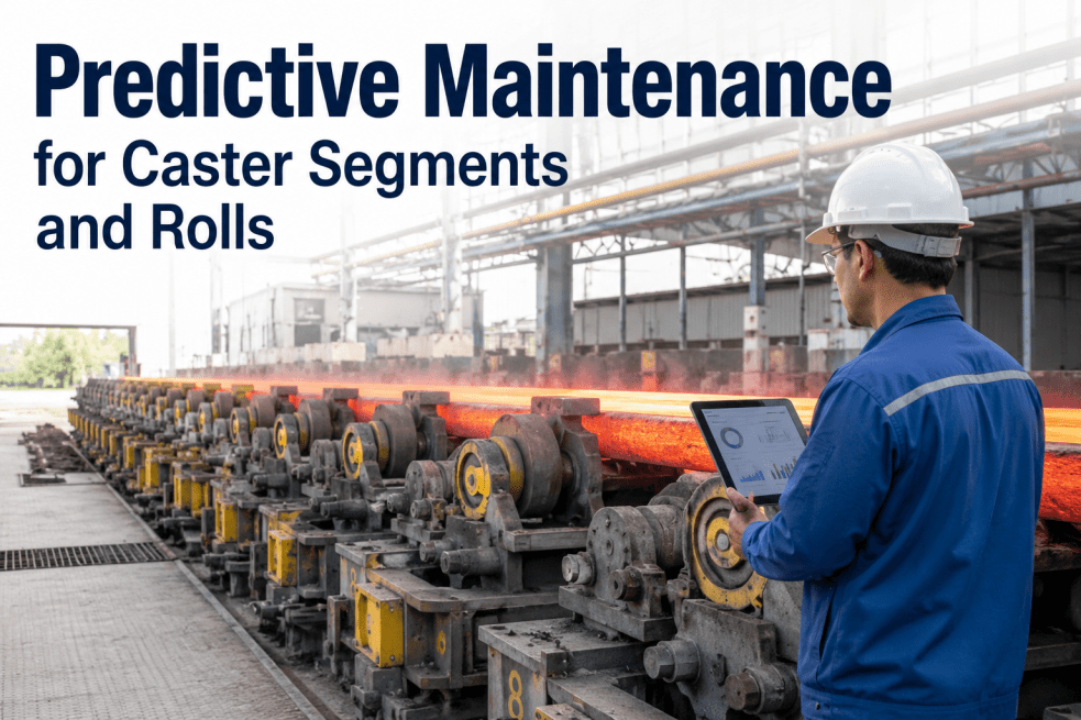
Beyond real-time breakout prevention and quality analytics, continuous casting machine performance over a campaign depends on the planned management of three major equipment categories — mold assemblies, strand guide segments, and oscillation systems — each with distinct wear mechanisms, condition signals, and maintenance scheduling requirements. iFactory's caster equipment tracking platform maintains continuous condition records for every mold, segment, and oscillator in service, generating planned maintenance recommendations based on condition rather than fixed service intervals. Book a Demo to see the full equipment lifecycle tracking dashboard.
Expert Review: What Caster Operations With the Lowest Breakout Rates Do Differently
After working with continuous casters across U.S. and Canadian integrated and EAF steel operations for twenty-two years, the performance difference between casters that run 18 months between breakout events and those that experience two or three per year comes down to one operational distinction: the first group treats their mold thermocouple data as a continuous real-time analytics feed, and the second group treats it as an alarm system. The distinction sounds minor. The operational reality is enormous. When you treat the TC data as an alarm system, you are waiting for a parameter to cross a fixed threshold — which in most cases means you have 2 to 4 minutes of response time between the alarm and the breakout, and your only option is an emergency strand arrest that itself causes a quality event. When you treat the TC data as a real-time analytics feed with a trained detection model running continuously, you get 6 to 10 minutes of actionable lead time — enough to do a controlled speed reduction, get the mold powder consumption back up, and let the shell condition recover without a strand arrest. The second thing the top performers do consistently is connect their breakout prevention system to their mold change scheduling. Their breakout prevention system is not just predicting breakouts — it is accumulating mold condition data per heat and recommending mold changes based on actual TC performance degradation rather than a fixed tonnage schedule. That connection eliminates the scheduled mold changes that happen when the mold is still in good condition and the undetected mold degradation events that happen when a mold runs past its actual condition limit. Both of those improvements require exactly the same data that every modern caster is already collecting. The only missing piece is the analytics platform that uses it correctly.
— Continuous Casting Operations and Process Engineering, U.S. Flat-Rolled Steel, iFactory Analytics Reference 2026Conclusion
Continuous casting machine analytics and breakout prevention is the highest-consequence preventive analytics application in a steel melt shop. A $1.8 to $4.5 million breakout event that the mold thermocouple array was already generating the precursor signal for — 4 to 12 minutes before the event — is not a failure of sensor coverage. It is a failure of analytics infrastructure. iFactory's casting analytics platform closes that gap by applying four simultaneous breakout detection models to the continuous data stream from the mold thermocouple array, friction measurement system, and Breakout Risk Score integration across tundish condition and spray cooling status — delivering speed reduction commands before the failure threshold is crossed rather than alarms after it is.
The 94% breakout reduction and 28% internal defect rate reduction at comparable caster deployments are the documented result of converting existing mold, segment, and process sensor data into real-time casting intelligence rather than historical alarm logs. The platform deploys on existing caster automation without new sensor hardware at most installations, establishes grade-specific detection model baselines within the first 30 casting sequences, and integrates with your CMMS to place every condition-triggered maintenance recommendation in the scheduler's queue before the service window closes. Book a Demo to see what iFactory's caster analytics would deliver on your specific machine and product mix.
Frequently Asked Questions
iFactory's breakout detection models are designed to deliver useful protection across the full range of mold thermocouple configurations found in U.S. caster installations — from older casters with 20 to 40 thermocouples in a single row per face, to modern casters with 80 to 160 thermocouples across multiple rows in a matrix configuration. The asymmetric heat transfer detection model performs best with multi-row matrix configurations that enable the propagation velocity analysis.
False alarm management is the critical performance metric for breakout detection systems — a system that prevents breakouts but generates 6 to 8 unnecessary speed reductions per shift will be overridden by operators within weeks, negating its protective value. iFactory's compound Breakout Risk Score architecture is specifically designed to minimize false positives by requiring multi-signal confirmation before automatic speed reduction is triggered. The BRS above 80 threshold that triggers automatic speed reduction requires simultaneous contributions from at least two of the four detection models.
iFactory creates a heat-by-heat slab condition record that links every slab's identity (heat number, strand, cut sequence position) to the caster condition parameters that were active during its casting: BRS maximum value, mold TC asymmetry index, spray zone balance score, segment gap deviation maximum, tundish temperature deviation, and oscillation friction index. This condition record travels with the slab identity through the downstream tracking system — connected to the slab yard management system via API or flat file export in the format used by your specific Level 2 slab tracking infrastructure.
Yes — iFactory's data integration architecture supports the full range of caster automation vintages found in U.S. steel operations, from modern OPC-UA capable Level 2 systems (Siemens, ABB, Primetals, Danieli) to older PI historian-based installations and direct PLC connectivity via Modbus or Profibus. For casters with no existing historian, iFactory deploys an edge data collection node that connects directly to the caster's PLC rack via read-only Modbus TCP, capturing thermocouple readings, oscillation signals, spray flow meters, and segment position data at 1-second intervals without any modification to the caster control system.
For a two-strand slab caster with existing mold thermocouple systems, oscillation measurement, spray cooling flow meters, and Level 2 historian connectivity, iFactory's complete deployment runs $88,000 to $175,000 depending on the automation platform, data connection complexity, and scope of slab tracking integration. The cost breaks into caster data integration and historian connection ($22,000–$48,000), iFactory platform configuration including BRS model calibration by grade.