On a high-mix electronics assembly line in Penang, a single operator working the night shift installed a left-side cable bracket where the right-side version belonged. The bracket seated cleanly, the torque wrench clicked at 4.2 Nm, and the unit passed down the line — until field failure analysis six weeks later traced a 0.3% warranty claim spike back to that one station. The root cause was not negligence. It was a paper work instruction revised three days earlier that never reached the floor, sitting in a supervisor's inbox while operators followed the previous revision. This is how most assembly errors actually happen: not from careless workers, but from guidance systems that cannot verify, cannot update, and cannot confirm what was actually done.
Every step verified before the next one unlocks
Replace paper SOPs with guided digital instructions that integrate pick-to-light, vision presence checks, and torque-tool verification — running on-prem inside your plant network, with per-unit build history recorded to MES via API.
The cost of assembly errors
Assembly errors compound downstream. A wrong fastener installed at station 4 becomes a rework event at station 12, a functional test failure at station 18, and a field return at the customer site 40 days later. The further an error travels, the more it costs — by a factor that follows a predictable escalation curve.
Cost escalation per defect, by detection stage. The ratio between station-level detection and field detection typically exceeds 2,800x in discrete electronics assembly.
Why paper instructions fail
Paper SOPs are static documents in a dynamic environment. They cannot confirm a part was picked, cannot verify a torque value was achieved, and cannot tell you which operator followed which revision on which serial number. The failure modes are structural, not incidental.
Guided digital instructions
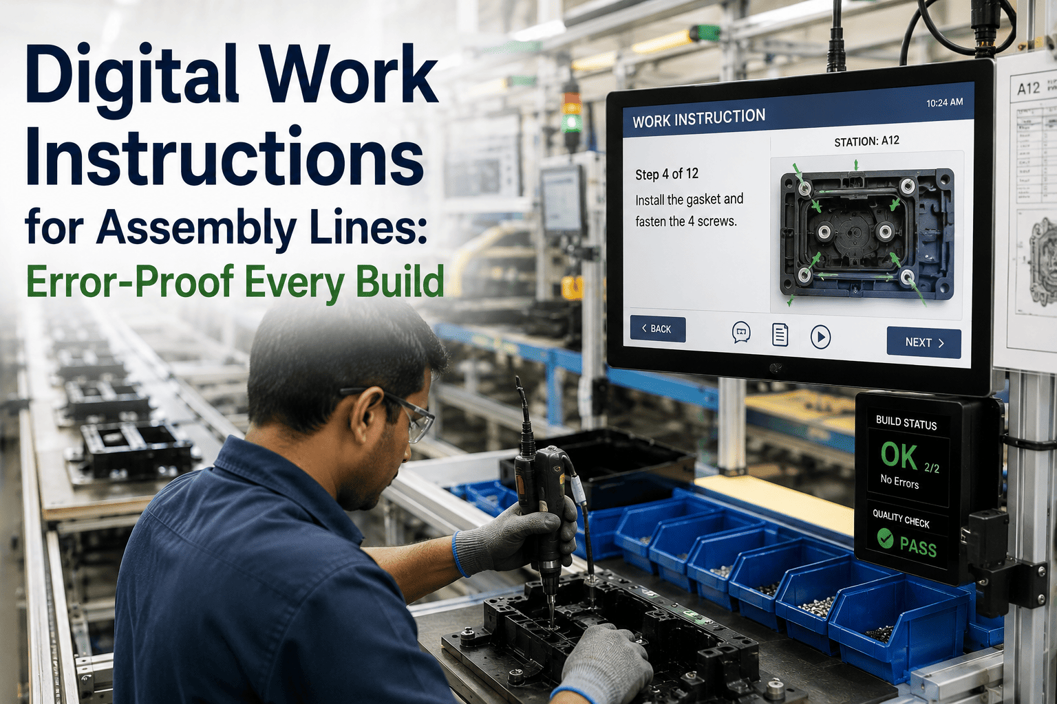
A guided instruction is not a PDF on a screen. It is a sequential workflow where each step presents exactly one task, waits for confirmation, and only then advances. The operator's cognitive load drops because the screen shows what to do now — not everything that could ever be done.
A guided instruction sequence. Each step gates the next — the operator cannot skip ahead, and the system cannot advance without verified completion.
Built-in error proofing
Error proofing means the system makes the wrong action physically or logically impossible. Three layers — pick confirmation, vision presence, and torque verification — work in sequence so that a defect cannot leave the station undetected.
Pick Confirmation
Pick-to-light indicators and barcode scanners verify the operator selected the correct part from the correct bin before the step advances. Eliminates wrong-part errors — the single largest defect category in manual assembly.
Vision Presence Check
A camera at the station captures an image after each step. A vision model — running on the on-prem NVIDIA AI server — verifies that the correct part is installed, oriented correctly, and fully seated. Catches missing screws, inverted brackets, and misaligned connectors.
Torque Verification
DC electric torque tools transmit the achieved value, angle, and timestamp for each fastener via OPC-UA or direct integration. The step does not unlock until every fastener falls within the specified torque window — under-torque and over-torque both block advancement.
Station-level error-proofing coverage across a typical 40-step assembly process. The combined gate — all three layers in sequence — catches defects that any single layer would miss.
Per-unit traceability
Every action taken on every serial number is recorded: which operator, which instruction revision, which torque values, which vision results, at what timestamp. This is not log data — it is a structured build history attached to the unit itself, queryable by serial number and exportable to MES.
Per-unit verification heatmap across 20 assembly steps. Darker cells indicate higher confidence readings. Marginal cells are retained in the build record for quality trend analysis — they are not failures, but they are not invisible either.
| Serial | Step | Operator | Revision | Torque (Nm) | Vision | Timestamp |
|---|---|---|---|---|---|---|
| SN-2024-08472 | 03 — Screw install | OP-2147 (L. Chen) | r-2024.03.12 | 1.79 / 1.81 / 1.80 / 1.82 | Pass (0.97) | 14:22:08 |
| SN-2024-08472 | 04 — Bracket seat | OP-2147 (L. Chen) | r-2024.03.12 | — | Pass (0.94) | 14:22:41 |
| SN-2024-08472 | 07 — Cable route | OP-2147 (L. Chen) | r-2024.03.12 | — | Marginal (0.71) | 14:24:15 |
| SN-2024-08472 | 12 — Final torque | OP-2147 (L. Chen) | r-2024.03.12 | 4.18 / 4.21 / 4.20 | Pass (0.96) | 14:27:33 |
Excerpt from the per-unit build record. Every field is written automatically — operators never fill in logs. The API pushes this structure to MES in real time, so downstream stations and quality systems see the same data.
Rolling out and updating instructions
The highest-value feature of digital work instructions is not the screen at the station — it is the ability to change what appears on that screen without reprinting, redistributing, or retraining. When an engineering change order lands, the updated instruction goes live across every station running that recipe in under 30 seconds.
The same update mechanism supports operator training. New operators can run a recipe in a guided practice mode where mistakes are caught and coached in real time, without producing scrap. The system records which steps each operator has verified proficiency on, so you can prove readiness before they touch a production unit.
The AI assistant runs on the on-prem NVIDIA server, so this conversation never leaves the plant network. It can read the current instruction revision, the part catalog, and the live build state — but it cannot send data externally.
Benchmarks and roadmap
Across 1,000+ industrial deployments, the pattern is consistent: digital work instructions with integrated error proofing reduce assembly defects by 60–80% within the first quarter, and cut new-operator ramp-up time roughly in half. The deployment roadmap is structured to reach production in 6–12 weeks.
The system runs entirely inside your plant network. The NVIDIA AI server sits in your rack room. No instruction data, no vision images, and no operator interactions leave the facility. Integration to MES is via REST API or OPC-UA, depending on your existing stack.
Want to see the deployment plan mapped to your specific line? Book a 30-minute scoping call — we will bring a station audit template.
Frequently asked questions
Can digital work instructions integrate with our existing torque tools and PLCs?
Yes. The system connects to DC electric torque tools via OPC-UA, EtherCAT, or proprietary protocols depending on the manufacturer. PLC integration uses OPC-UA or Modbus TCP. We have pre-built adapters for Atlas Copco, Bosch Rexroth, KUKA, and Mitsubishi tooling, among others. If your tool transmits a torque value, we can read it.
Does the system run on-prem or in the cloud?
On-prem. The AI server — a pre-configured NVIDIA unit — is racked in your facility. All instruction data, vision images, torque logs, and operator interactions stay inside your plant network. The only external connection is optional: a telemetry feed to our support team for proactive monitoring, which you can disable.
How long does it take to digitize an existing paper SOP?
A typical 40-step assembly recipe takes 2–4 hours to digitize in the instruction builder, assuming photos and diagrams are available. Complex recipes with branching logic or variant-dependent steps take longer. Our team handles the first few recipes during deployment; your engineers take over after a half-day training session.
What happens if the network or server goes down?
Each station has a local cache of the current recipe and can operate for up to 72 hours without the central server. Torque and pick data are buffered locally and synced when connectivity restores. The system is designed for 99.9% uptime, but the fail-safe mode ensures the line keeps running even during an outage.
Can operators override or skip steps if they know better?
Steps can be overridden only with a supervisor badge scan, and every override is logged with timestamp, supervisor ID, and reason code. The system never silently allows a skip. This preserves the error-proofing guarantee while giving experienced operators a path to handle edge cases without halting the line.
How does the system handle multilingual operators?
Each recipe supports multiple language versions of text fields. The operator selects their language at login, and all subsequent instructions display in that language. Photos, diagrams, and video are language-agnostic. We support any language with a standard Unicode font — including right-to-left scripts.
Stop documenting errors after the fact. Prevent them at the station.
Book a 30-minute demo and we will map your highest-error assembly steps to a digital work instruction workflow — with pick confirmation, vision checks, and torque verification gated to your exact recipe.



.png)