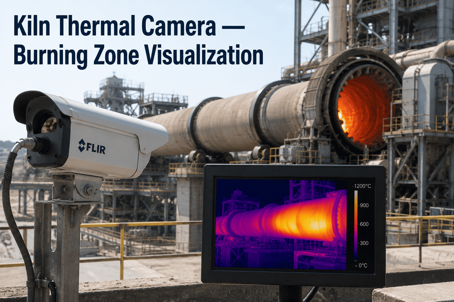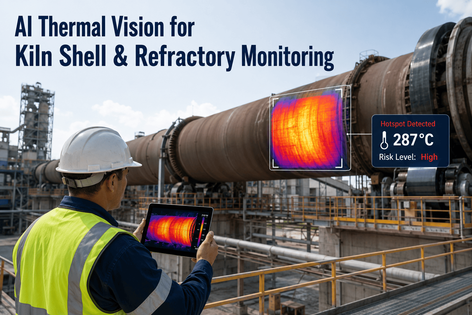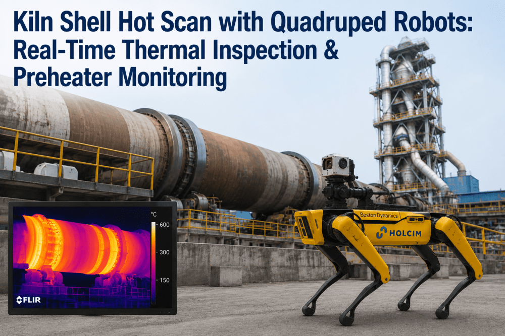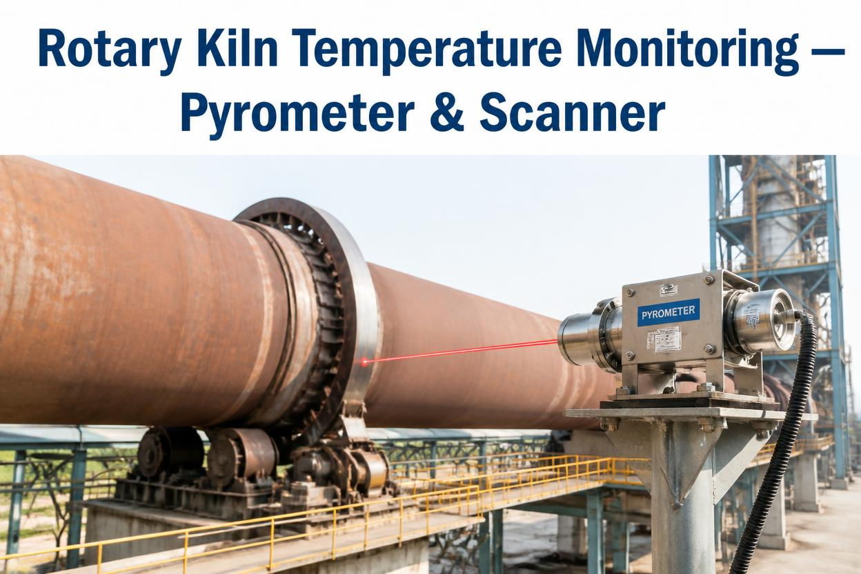
The inside of a cement kiln reaches temperatures that would destroy almost any sensor placed directly in the flame, which is exactly why plants rely on two very different measurement technologies to keep the burning zone under control: pyrometers that read the flame and clinker bed from outside the kiln, and infrared shell scanners that read heat escaping through the refractory from the outer steel surface. Used together, they tell an operator both what's happening at 1,450°C inside the kiln and how much of that heat is quietly eating through the brick lining protecting the shell. Used separately, each one only tells half the story. If your kiln is still running on handheld readings or a single-point sensor, book a demo to see what continuous coverage actually catches.
600–1,800°C
200–350°C
Above 400°C
Two Instruments, Two Different Views of the Same Kiln
It's a common misconception that a pyrometer and a shell scanner do the same job at different price points. They actually measure entirely different things, and a complete kiln monitoring setup needs both rather than treating one as a substitute for the other.
What a Pyrometer Protects: Clinker Quality and Fuel Efficiency
Burning zone temperature directly determines clinker quality — too cold and the chemical reactions that form clinker minerals don't complete properly, too hot and the plant burns excess fuel while accelerating refractory wear. A two-color pyrometer covering the 600–1,800°C range gives operators the real-time feedback needed to keep the flame and fuel-air mixture tuned, catch incomplete combustion before it shows up in NOx emissions, and view material size and shape at the kiln outlet as an additional quality check.
What a Shell Scanner Protects: Refractory Life and Shell Integrity
Shell temperature is a direct proxy for how much brick is left between the flame and the steel shell. A healthy refractory section typically holds shell temperatures around 200–350°C. As bricks wear down, that number climbs — reaching roughly 350–400°C at about 30% brick loss and 400–450°C near 50% loss. Beyond 450–460°C, the risk of a shell burn-through becomes a genuine emergency, since steel begins losing structural integrity above 400°C.
What a Scanner Catches Beyond Simple Hot Spots
| Signal | What It Typically Indicates |
|---|---|
| Localized hot spot | Brick loss, spalling, or a coating detachment at a single point |
| Gradual zone-wide temperature rise | Protective clinker coating thinning across a broader section |
| Thermal warp or distortion pattern | Mechanical or thermal stress in the shell, especially near tyres |
| Rotational speed variance along kiln length | A twist condition developing that can cause mechanical damage |
| Tyre slip below normal thresholds | Movement issues most critical during heat-up and cool-down phases |
Coverage Gaps Most Plants Don't Notice Until It's Too Late
Even a well-installed scanner system can leave portions of the shell effectively invisible. Structural obstructions like support pillars, secondary air ducts, and platforms create shadow zones where a single scanner simply can't see the shell surface, and a hot spot developing inside a shadow zone can progress significantly before anyone notices. Kilns longer than roughly 60 meters generally need multiple scanning positions with overlapping fields of view specifically to close these blind spots, rather than relying on one wide-angle unit to cover the entire length.
Choosing Between Fixed Arrays and Pan-Tilt Robotic Scanners
Plants weighing a shell scanner installation typically choose between fixed infrared scanner arrays and motorized pan-tilt robotic systems, and each approach makes a different trade-off between coverage and cost. A fixed array mounted at a single position gives continuous, uninterrupted monitoring of whatever section falls within its field of view, but longer kilns often need several fixed units to eliminate shadow zones from support structures. A pan-tilt robotic scanner can cover a wider circumference from a single mounting point by physically sweeping across the kiln surface, which reduces the number of units needed but introduces a scan cycle time — meaning any single point on the shell is only checked periodically rather than continuously. For kilns where hot spots can develop and progress quickly, that gap between scan cycles matters more than it might on a more thermally stable line. Many plants land on a hybrid approach: fixed scanners covering the highest-risk zones like the burning zone and tyre sections, supplemented by a pan-tilt unit sweeping the remaining length for broader coverage at lower cost.
Integrating Data Into the Control Room
A scanner or pyrometer that produces excellent data is only as useful as the operator's ability to act on it in real time. Integration through standard protocols like OPC lets shell temperature, alarm status, and rotational speed data flow directly into the plant's existing distributed control system, so operators see kiln thermal health alongside the process variables they're already monitoring rather than needing to check a separate standalone system. Historical data logging matters just as much as the live feed, since trend analysis over weeks and months is what eventually feeds refractory life prediction models and energy loss tracking. Plants that treat their scanner and pyrometer data as a standalone alarm system, disconnected from broader kiln analytics, tend to capture only a fraction of the value the sensors are actually generating — the real payoff comes from combining thermal data with drive current, vibration, and production data in one connected view.