A switchgear room failure does not announce itself. It builds — a connection running 12°C above ambient, a faint ionization smell that technicians attribute to normal operation, a partial discharge event captured by no instrument because no instrument is installed. By the time a fault arc occurs or smoke triggers a detector, the equipment is already destroyed and the outage is already in progress. The inspection gap is not a staffing problem. It is visibility problem: power plant electrical rooms are inspected on weekly or monthly rounds, and everything that happens between those rounds is invisible to the maintenance program.
AI vision inspection changes the detection geometry entirely. Continuous camera-based monitoring of switchgear rooms — integrating thermal imaging, visual anomaly detection, smoke and arc flash precursor identification, and access control analytics — converts the spaces between manual rounds into a continuously monitored data stream. When that stream feeds into an AI-driven electrical analytics platform, individual camera alerts become part of compound asset health picture that directs maintenance resources to the right equipment before failure occurs. This article covers how AI vision inspection works in power plant switchgear environments, what it detects, how it integrates with existing analytics platforms, and what U.S. plant operators need to evaluate before deployment.
AI Vision Analytics · Power Plant Electrical Rooms
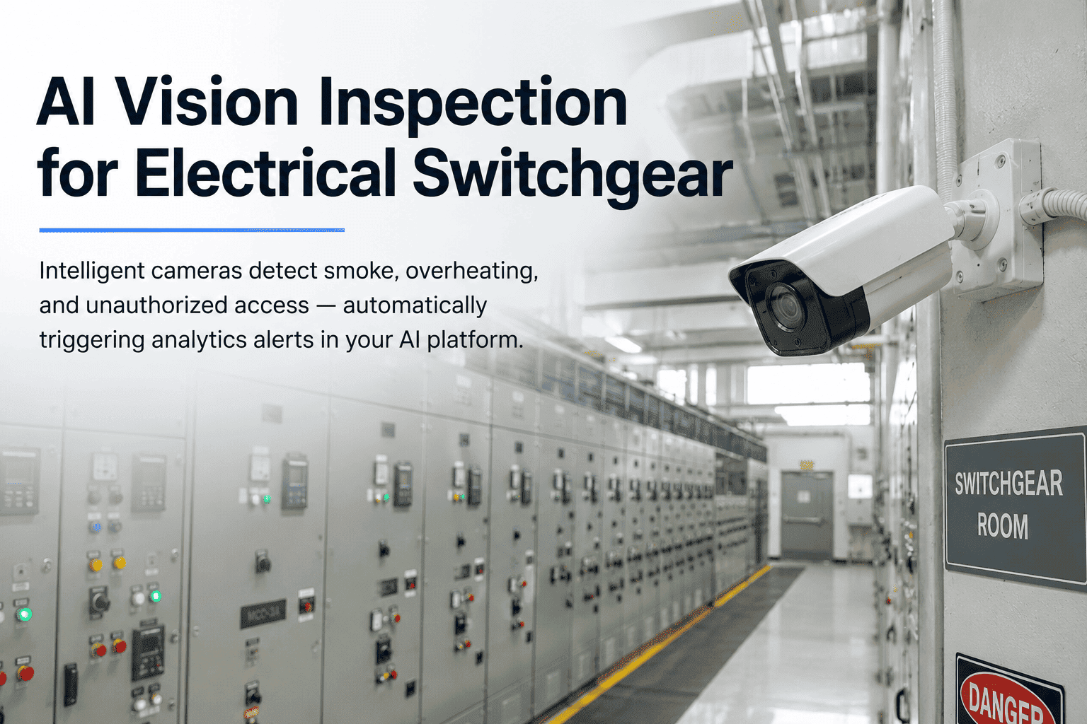
AI Vision Inspection for Electrical Switchgear in Power Plants
Continuous camera-based monitoring for smoke detection, thermal anomalies, arc flash precursors, and unauthorized access — integrated directly into your AI-driven electrical analytics platform.
Sources: IEEE Std 3007.2 · NFPA 70B · EPRI Electrical Equipment Reliability Data · iFactory Deployment Data 2026
The Inspection Gap That Manual Rounds Cannot Close
Power plant switchgear rooms are inspected by qualified personnel on scheduled rounds — typically daily or weekly visual checks, supplemented by periodic thermographic surveys conducted once or twice per year. This inspection model was designed around the assumption that degradation progresses slowly enough that periodic observation is sufficient to catch developing problems. That assumption is wrong for a significant subset of failure modes, and the consequences of that gap are measurable in the incident data.
72%
of arc flash events in industrial electrical rooms are preceded by detectable thermal anomalies
IEEE reliability data shows the majority of switchgear arc flash incidents have a thermal precursor period ranging from hours to weeks — a window that continuous thermal monitoring captures and manual rounds miss.
IEEE Std 3007.2
168 hrs
average time between manual inspection rounds in a typical power plant switchgear room
Weekly inspection intervals are standard practice at many plants. A thermal fault developing on a Tuesday afternoon is undetected until the following Monday morning round — if it hasn't already failed.
Industry Survey Data
$2.4M+
average cost of a major switchgear failure event including emergency response and replacement
EPRI all-in cost data for major electrical failures at utility-scale plants includes emergency labor, replacement equipment at spot pricing, lost generation, and regulatory reporting costs.
EPRI Reliability Data
2× yearly
typical thermographic survey frequency — leaving 363 days per year without thermal imaging coverage
Semi-annual IR surveys are the NFPA 70B recommended minimum for critical switchgear. AI vision with continuous thermal imaging provides the coverage that semi-annual surveys cannot.
NFPA 70B
The inspection gap is not a criticism of maintenance teams — it is a structural limitation of the periodic inspection model applied to equipment that can degrade on a timescale shorter than the inspection interval. AI vision inspection does not replace manual rounds. It fills the 167 hours between them with continuous monitoring that catches what rounds miss.
Ready to see how AI vision integration fits your switchgear monitoring program? Book a 30-minute architecture review with iFactory's power plant electrical team.
What AI Vision Systems Detect in Switchgear Environments
AI vision inspection for power plant switchgear is not a single technology — it is a layered detection architecture combining multiple imaging modalities, each targeting a specific failure precursor or safety condition. Understanding what each layer detects, and at what point in the failure progression it detects it, is essential for evaluating platform capability and deployment scope.
Detection Layer 01
Continuous Thermal Imaging and Hotspot Detection
Fixed thermal imaging cameras mounted in switchgear rooms provide continuous temperature monitoring of bus connections, breaker compartments, cable terminations, and transformer bushings. AI algorithms analyze each thermal frame against baselines calibrated at known-good conditions, flagging temperature rises above configurable delta thresholds and identifying spatial patterns consistent with specific fault types — loose connections, overloaded conductors, failing contacts. Unlike manual IR surveys, continuous thermal imaging catches anomalies at any hour of any day.
Delta-T threshold alerting — configurable by equipment class and criticality
Load-normalized temperature analysis to eliminate false positives from load variation
Thermal trend tracking — rate-of-change alerts as well as absolute thresholds
Automatic NFPA 70B thermographic inspection report generation from camera data
NFPA 70B threshold for elevated concern on bolted connections — auto-flagged by AI
Weeks–months
Lead time between detectable thermal anomaly and connection failure in switchgear
Continuous
vs. twice-yearly manual IR survey — coverage gap eliminated
Detection Layer 02
Smoke Detection, Arc Flash Precursors, and Ionization Events
Visual AI models trained on power plant electrical room imagery can detect smoke particulates at concentrations far below visible threshold — catching incipient insulation heating before it reaches the combustion stage. Ultraviolet-sensitive cameras detect corona discharge and ionization events that precede arc flash incidents. Combined with thermal imaging, these detection layers create a multi-modal early warning system that activates well before conventional point-type smoke detectors or fire suppression systems trigger.
Sub-threshold smoke detection — visual AI identifies particulate haze before visible smoke
UV-band corona discharge detection for medium and high-voltage equipment
Alert-to-notification latency under 30 seconds — enabling protective action before suppression activates
Integration with plant fire alarm and emergency notification systems
<30 sec
Alert-to-notification latency for smoke and arc precursor events
Pre-smoke
Detection stage — visual AI identifies incipient heating before conventional detectors activate
NFPA 72
Integration with fire alarm systems per NFPA 72 requirements
Detection Layer 03
Visual Condition Monitoring and Structural Anomaly Detection
Beyond thermal and smoke detection, AI vision systems analyze high-resolution visual imagery of switchgear compartments to identify physical condition changes — oil staining on transformer bushings, condensation accumulation inside panels, door seal degradation, physical damage from vibration or seismic events, and indicator light status changes. Change detection algorithms compare current imagery against calibrated baseline photographs, flagging any visual deviation for human review. This converts the camera system into a continuous visual inspection function that operates between manual rounds.
Baseline image comparison — flags any physical change in compartment appearance
Indicator light and position indicator status monitoring — auto-logs state changes
Oil and fluid staining detection on transformer and cable termination areas
Condensation and water ingress detection in switchgear panel interiors
Automatic inspection log generation from camera-detected events for CMMS work order creation
Continuous
Visual inspection coverage replacing weekly or monthly manual round observations
Auto-log
Every camera-detected change generates a timestamped inspection record in the analytics platform
CMMS
Work orders auto-generated from visual anomaly detections — routed to responsible technician
Detection Layer 04
Unauthorized Access Detection and Personnel Safety Monitoring
Switchgear rooms in power plants are restricted areas with specific personnel qualification and PPE requirements under OSHA 1910.269 and NFPA 70E. AI vision systems integrated with access control infrastructure monitor for unauthorized entry, verify PPE compliance before personnel approach energized equipment, and maintain a complete access log with visual record. For NERC CIP-compliant facilities, camera-based access monitoring contributes to physical security perimeter documentation requirements for Electronic Security Perimeter-adjacent areas.
Unauthorized access detection with immediate control room alert
PPE compliance verification — arc flash suit, face shield, and glove detection at entry
Timestamped visual access log — every entry and exit recorded with image evidence
NERC CIP physical security audit trail auto-generated from access log data
Lone worker monitoring — alert if personnel remain in room beyond defined time without check-in
OSHA 1910.269
PPE verification aligns with OSHA electrical safety requirements for power generation
NERC CIP
Physical access log contributes to CIP-006 physical security documentation requirements
100%
Entry/exit events captured with visual record — eliminates access log gaps
Integration Architecture: How Vision Alerts Feed the Analytics Platform
An AI vision system that operates in isolation — generating alerts that land in a separate monitoring console — delivers only a fraction of its potential value. The highest-value deployment architecture integrates vision alerts directly into the electrical analytics platform, where they become inputs to compound asset health scores, trigger permit-to-work workflows, and build a continuous inspection record alongside sensor-based and periodic test data. The integration workflow below describes how that architecture operates in practice.
01
Camera Data Capture and Edge Processing
Fixed thermal and visual cameras in switchgear rooms transmit continuous image streams to an edge processing unit — typically a ruggedized compute node installed in the electrical building. Edge processing runs AI inference locally, reducing bandwidth requirements and eliminating cloud latency for time-critical alerts. Thermal frames are analyzed at up to 30 frames per second; high-resolution visual frames are analyzed at configurable intervals. Edge units continue operating during network interruptions, buffering alerts for transmission on reconnection.
02
Alert Classification and Severity Scoring
Detected anomalies are classified by the AI model into event categories — thermal hotspot, smoke precursor, corona discharge, visual change, access event — and assigned a severity score based on the magnitude of the deviation from baseline, the criticality of the affected equipment, and the historical failure correlation for that event type on similar assets. A 15°C temperature rise on a 138kV bus termination scores differently than the same rise on a 480V lighting panel feeder. Severity-based routing ensures high-consequence alerts reach the right person immediately.
03
Analytics Platform Integration and Health Score Update
Classified vision alerts are transmitted to the electrical analytics platform via API, where they are mapped to the relevant asset in the equipment register. A thermal hotspot alert on a specific breaker compartment updates that breaker's composite health score, combining with existing contact resistance trend data, partial discharge history, and operation count to produce a revised overall asset health assessment. Vision data fills the continuous monitoring gap that sensor-based analytics alone cannot cover for all asset types.
04
Work Order Generation and Maintenance Routing
Vision-triggered alerts above configured severity thresholds automatically generate work orders in the connected CMMS system. Work orders include the camera image evidence, thermal data, asset identification, recommended inspection scope, and required PPE based on the equipment's arc flash hazard classification. For switchgear identified as requiring panel entry, the work order automatically links to the permit-to-work system, ensuring that LOTO and electrical safety procedures are followed before any remedial work begins.
05
Compliance Documentation and Audit Trail Generation
Every camera-detected event — thermal scan, visual inspection pass, access event, alert-to-resolution workflow — is automatically recorded in the analytics platform with timestamp, image evidence, and resolution action. NFPA 70B thermographic inspection reports are generated directly from continuous camera data, documenting the date, time, equipment identified, temperature readings, and any corrective actions taken. For NERC CIP facilities, access logs with visual evidence are formatted for CIP-006 physical security compliance documentation.
Ready to see how AI vision integration fits your switchgear monitoring program? Book a 30-minute architecture review with iFactory's power plant electrical team.
Compliance Impact: What Continuous Vision Monitoring Satisfies
AI vision inspection is not deployed purely as a safety technology — it also addresses specific documentation requirements across multiple compliance frameworks that apply to power plant electrical maintenance. The table below maps each compliance obligation to what continuous camera monitoring contributes toward satisfying it.
Standard
Requirement
How Vision Monitoring Contributes
Documentation Frequency
NFPA 70B
Thermographic inspection of electrical equipment at defined intervals
Continuous thermal imaging replaces or supplements semi-annual IR surveys; auto-generates inspection reports with temperature data and hotspot imagery
Continuous — report on demand
OSHA 1910.269
Electrical safety work practices for power generation — PPE and access controls
PPE compliance verification at switchgear room entry; access log with visual evidence; lone worker monitoring for personnel safety
Per-entry log — continuous
NERC CIP-006
Physical security of BES Cyber System facilities — access monitoring and logging
Timestamped access log with image evidence for all switchgear room entries; unauthorized access alerting; 90-day retained record for audit
90-day rolling retention
NFPA 72
Fire alarm system — early warning detection in electrical equipment rooms
Sub-threshold smoke and thermal detection feeding into fire alarm system integration; alert lead time before conventional point detectors activate
Continuous — event-based log
IEEE 3007.2
Maintenance of industrial and commercial power systems — recommended practice
Continuous condition data contributes to condition-based maintenance program documentation; thermal trend records support maintenance interval justification
Continuous — trend record
Ready to see how AI vision integration fits your switchgear monitoring program? Book a 30-minute architecture review with iFactory's power plant electrical team.
Deployment Considerations: Camera Selection, Placement, and Integration Requirements
AI vision inspection deployments in switchgear rooms involve hardware selection, physical placement planning, and integration decisions that determine whether the system delivers its full detection capability or leaves coverage gaps. The checklist below covers the critical evaluation points that plant engineers and safety managers should work through before finalizing a deployment scope.
Camera Hardware Selection
Thermal resolution and sensitivity. Minimum 320×240 thermal resolution for switchgear room applications; 640×480 preferred for high-voltage equipment with smaller thermal targets. Sensitivity specification (NETD) should be 50 mK or better for reliable 3°C delta-T detection at distance.
Environmental rating. Switchgear rooms have dust, humidity, and in some plants chemical exposure from SF6 handling. Camera enclosures should meet minimum IP54 rating; IP66 for high-humidity environments such as underground cable vaults or rooms adjacent to cooling water systems.
Dual-band capability. Cameras combining thermal and high-resolution visible imaging in a single unit simplify installation and reduce cable runs. The visible band provides context for thermal anomaly location identification that thermal-only cameras cannot offer.
Coverage Planning and Placement
Panel face coverage vs. termination coverage. Panel face cameras monitor indicator lights, door seals, and overall compartment condition. Separate cameras positioned to view cable termination areas and bus connections capture the thermal data most relevant to connection integrity — these are different pointing angles and should be planned separately.
Distance-to-spot size ratio. Thermal cameras have a specified IFOV (instantaneous field of view) that determines the minimum detectable target size at a given distance. Verify that the planned camera mounting distance resolves individual connection points at the target switchgear at the specified thermal resolution — this calculation is required before finalizing mounting positions.
Entry point coverage for access monitoring. Access detection cameras should cover all room entry and exit points with sufficient resolution for PPE classification — a minimum of 80 pixels across the torso at the entry point for reliable PPE detection by the AI model. Wide-angle lenses at door-height mounting points typically satisfy this requirement.
Network and Integration Requirements
OT/IT network segmentation. Camera systems in switchgear rooms must be installed on a network segment that is isolated from the control system network. Edge compute units communicate outbound to the analytics platform via encrypted tunnel without inbound access paths that could affect plant operations. NERC CIP facilities require this architecture to maintain Electronic Security Perimeter integrity.
Analytics platform API connectivity. Verify that the vision system's alert output format is compatible with the receiving analytics platform's ingestion API. iFactory's electrical analytics platform accepts vision alerts via documented REST API with standardized asset mapping — camera alert events are automatically associated with the correct asset in the equipment register without manual configuration per alert.
Close the Inspection Gap · Automate Compliance Documentation · Reduce Forced Outages
See AI Vision Inspection Working Inside an Electrical Analytics Platform
We walk through your switchgear room layout, map the coverage plan, and show exactly how camera alerts feed into health scores, work orders, and NFPA 70B compliance reports — with your actual equipment configuration as the reference.
Senior Electrical Systems Engineer, Generation Asset Management
IEEE Senior Member · NFPA 70E Qualified Person · 18 years power plant electrical maintenance
The argument I hear most often against continuous camera monitoring in switchgear rooms is that it is solving a problem that manual rounds already address. That argument collapses immediately when you look at the incident timelines. In every switchgear fire or arc flash event I have reviewed post-incident, the thermal precursor was present and detectable for hours or days before the failure. The manual inspection that preceded it missed it — not because the inspector was negligent, but because the round happened 48 hours earlier and the fault developed between visits. The second argument I hear is that camera systems generate too many alerts and operators start ignoring them. That is true of poorly configured systems with fixed temperature thresholds and no load normalization. It is not true of AI platforms with dynamic baselines, severity scoring, and consequence-weighted routing. The plants I have seen deploy well-designed AI vision systems have reduced their thermal-origin failure rate materially, and their NFPA 70B compliance documentation is now a report pull rather than a multi-day exercise. The technology has matured to the point where the implementation risk is lower than the operational risk of not deploying it.
Review conducted April 2026 based on iFactory platform evaluation across four generation facilities including combined-cycle, coal, and peaker assets in the U.S. Midwest and Mid-Atlantic regions.
Ready to see how AI vision integration fits your switchgear monitoring program? Book a 30-minute architecture review with iFactory's power plant electrical team.
Conclusion — Continuous Visibility Is the Missing Layer in Switchgear Maintenance
The maintenance model that power plant electrical teams have operated under for decades — scheduled manual rounds, periodic thermographic surveys, calendar-based testing — was not designed for the detection of anomalies that develop on a timescale shorter than the inspection interval. AI vision inspection does not invalidate that model. It fills the gap between rounds with continuous automated monitoring that catches developing thermal faults, smoke precursors, visual condition changes, and access events in real time, every hour of every day.
The integration of vision alerts into an electrical analytics platform is what transforms camera systems from isolated safety devices into operational intelligence tools. When a thermal hotspot detected at 2 AM on a Tuesday updates a breaker's health score, triggers a work order, and links to a permit-to-work workflow — all without a person having to observe the alert and manually route it — the maintenance program gains the kind of continuous awareness that manual rounds can never deliver. For plants managing aging switchgear fleets, tightening NERC compliance obligations, and operating under capacity agreements that penalize forced outages, that visibility is not a feature addition. It is a fundamental upgrade to the risk management architecture of the facility.
Frequently Asked Questions
NFPA 70B does not currently specify that continuous camera-based thermography satisfies the same documentation obligation as a qualified thermographer conducting a calibrated manual IR survey — the standard was written around periodic manual inspection as the methodology. However, continuous thermal camera data can satisfy the underlying intent of the requirement (documented thermal inspection at defined intervals) when the camera system is properly calibrated, the images are maintained in a searchable record, and temperature readings are associated with specific equipment. The practical approach most plants take is to use continuous camera monitoring to reduce the required frequency of formal manual thermographic surveys and to generate interim documentation between annual or semi-annual qualified thermographer visits. Consult with your specific compliance authority for guidance on survey frequency reduction documentation requirements at your facility.
Load-normalized thermal analysis is a core capability in AI-driven thermal monitoring platforms — without it, a switchgear bus that runs 40°C above ambient at full load would generate continuous alerts during every peak demand period regardless of equipment condition. The AI model maintains a dynamic thermal baseline for each monitored asset as a function of load level, establishing the expected temperature at a given current loading from historical data. Alerts are generated when the measured temperature deviates from the load-predicted baseline by more than the configured threshold — not when it exceeds a fixed absolute temperature. This approach eliminates the majority of false positives associated with fixed-threshold systems. Additionally, rate-of-change alerting flags situations where temperature is rising faster than load increase would predict, catching developing faults before they reach absolute threshold levels.
The NERC CIP concern with camera systems in electrical rooms is real but manageable through proper network architecture. The risk is that a networked camera could become an attack vector into control system networks if it is placed on the same network segment as BES Cyber Systems. The solution is network segmentation: camera systems must be installed on a separate network segment with no direct connectivity to the control system LAN. Edge compute units that process camera data communicate outbound to the analytics cloud platform via an encrypted, unidirectional data path — there is no inbound command capability that could affect plant operations. This architecture keeps the camera system outside the Electronic Security Perimeter as defined by NERC CIP-005, while simultaneously contributing to physical security documentation requirements under CIP-006. iFactory's deployment architecture documentation includes the network topology specifications required for CIP compliance review at NERC-registered facilities.
Edge processing architecture is specifically designed to maintain detection capability independent of network connectivity. The edge compute unit installed in the electrical building runs the AI inference models locally, processes all camera feeds, generates alerts, and stores alert records with image evidence locally during any network interruption. Local alert routing — to a control room workstation on the plant LAN, or via a separate notification system — continues functioning without cloud connectivity. When network connectivity restores, all buffered alerts and image records are synchronized to the analytics platform automatically. The local storage capacity on standard edge units supports 72 hours or more of alert buffering depending on alert volume. Critical alerts — thermal events above high-severity thresholds — can be configured to trigger SMS or email notification via a secondary communication path independent of the primary analytics platform connection.
A single switchgear room deployment — covering one 480V MCC room or one medium-voltage switchgear lineup — typically involves 4–8 cameras (combining thermal and visual), one edge compute unit, and network integration work. Hardware and installation cost for this scope ranges from $35,000 to $75,000 depending on camera specification, room size, and network infrastructure requirements. Annual software licensing for the vision module integrated with the iFactory electrical analytics platform adds $12,000 to $28,000 per year depending on asset count and analytics scope. Deployment timeline from site survey to operational monitoring is typically 6–10 weeks. For a full plant covering multiple switchgear rooms and electrical buildings, costs scale roughly linearly with room count — bulk camera procurement and shared edge infrastructure reduce per-room costs at higher quantities. Contact iFactory for a site-specific cost estimate based on your switchgear room count and existing network infrastructure.