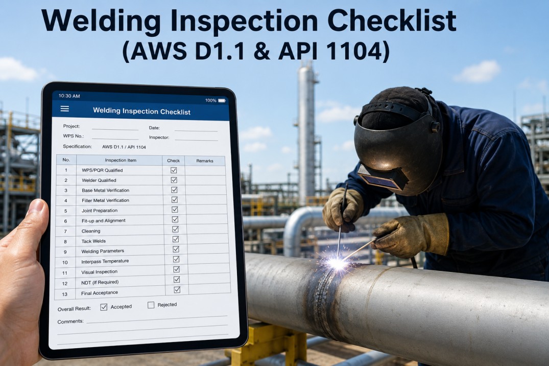
Welding Inspection Checklist (AWS D1.1 & API 1104)

By Valerie Collins on May 30, 2026

daily-equipment-inspection-checklist

Welding inspection failures cost far more than the welds themselves — rejected pressure vessels, structural connections that fail load testing, pipeline girth welds that require cut-out and repair, and AWS D1.1 nonconformances that ground a fabrication project until a Certified Welding Inspector signs off on corrective work. This checklist covers every inspection gate a CWI performs: pre-weld verification, in-process monitoring, visual examination, dimensional checks, and NDT hold points — structured to the requirements of AWS D1.1 Structural Welding Code and API 1104 Pipeline Welding Standard.

AWS D1.1
Structural Welding Code — Steel

API 1104
Pipeline Welding & Inspection

AWS D1.5
Bridge Welding Code

ASME Section IX
Pressure Vessel & Boiler
Tag legend:
CWI Hold Point Required Recommended NDT Required
CWI Hold Point items require a Certified Welding Inspector to physically verify and sign off before work may proceed. NDT items require documented nondestructive testing by a qualified technician.

Welding Inspection — iFactory

Digitize CWI Sign-Off, NDT Hold Points, and Weld Map Records — Every Joint Traceable from Fit-Up to Final Acceptance

iFactory's welding inspection module routes hold points to the CWI's tablet, captures digital sign-off with timestamp, links NDT reports to the weld joint record, and exports the complete weld package for AWS D1.1 and API 1104 documentation requirements.

Phase 01
Pre-Weld Inspection — Before the Arc Strikes
Every pre-weld nonconformance caught here costs minutes to correct. The same nonconformance found after welding can cost days. AWS D1.1 Clause 6.5 and API 1104 Section 9 both require documented pre-weld verification before production welding begins.

Welding Procedure Specification (WPS) is approved, current, and available at the weld station for the joint configuration being welded
CWI Hold Point
AWS D1.1 Clause 4 requires that welding be performed in accordance with a qualified WPS. The WPS must specify: base metal P-number, filler metal classification, preheat requirements, interpass temperature limits, welding position, current/polarity, and PWHT requirements where applicable. A welder working from memory rather than a visible WPS is a code violation regardless of the welder's qualification level.

Welder's qualification record (WQR/WPQ) is verified — qualified for the process, position, base metal, and thickness range being welded
CWI Hold Point
AWS D1.1 Clause 4.1 and API 1104 Section 6 require welder qualification testing. Qualification is position-specific, process-specific, and expires if the welder has not used the process within six months (AWS) or six months (API 1104). The CWI must verify that the qualification test record covers the exact configuration being welded — a 6G position qualification does not automatically cover all positions, and a qualification on 3/8-inch plate does not cover all thickness ranges.

Base metal material is verified against the Material Test Report (MTR) — heat number, grade, and specification confirmed against the drawing requirement
Required
Welding the wrong base metal grade invalidates the WPS qualification and may produce a weld joint with mechanical properties significantly below design requirements. For pressure-containing equipment and structural applications, heat number traceability to the MTR is required — not just grade marking on the material.

Joint fit-up dimensions verified: root opening, root face, bevel angle, and groove geometry match the WPS requirements and drawing tolerances
CWI Hold Point
AWS D1.1 Table 6.1 specifies dimensional tolerances for groove weld joint fit-up. Excessive root opening leads to burn-through or incomplete fusion. Insufficient root opening leads to incomplete joint penetration. Bevel angle deviations affect the ability to achieve complete fusion at the root. Fit-up dimensions must be measured with a weld gauge — not estimated visually.

Joint surfaces are clean — free of mill scale in the weld zone, paint, oil, moisture, rust, and other contaminants to the extent specified by the WPS
Required
AWS D1.1 Clause 5.15 specifies preparation requirements for weld surfaces. Moisture and hydrogen-containing contaminants are the leading cause of hydrogen-induced cracking (HIC) in high-strength steel welds. The cleaning zone must extend a minimum of 1 inch (25mm) on each side of the joint. Zinc-coated (galvanized) surfaces require special WPS qualification under AWS D1.3.

Preheat temperature is measured and confirmed to meet WPS minimum — measured at least 3 inches (75mm) from the weld joint on the base metal
CWI Hold Point
Preheat requirements in AWS D1.1 Table 4.5 are driven by base metal carbon equivalent and material thickness. Welding below minimum preheat temperature on hardenable steels produces a risk of hydrogen cracking, which may not manifest until 24–72 hours after welding and often goes undetected by visual inspection. Temperature must be confirmed with a calibrated contact pyrometer or temperature-indicating crayons — not by feel or visual heat estimation.

Filler metal classification, lot number, and condition verified against WPS — flux is dry, electrodes are stored correctly, FCAW wire is undamaged
Required
Low-hydrogen electrodes (E7018, E7016, E8018) require storage in a heated oven at 250–300°F (120–150°C) and exposure time limits after removal — typically 4 hours in ambient conditions before reconditioning is required. Wet electrodes are a leading cause of porosity and hydrogen cracking. API 1104 has specific filler metal requirements for pipeline girth welds that differ from AWS D1.1 structural applications.

Alignment and mismatch (hi-lo) of abutting pipe or plate edges is within specified tolerance before tack welding begins
Required
API 1104 Section 7.3 limits hi-lo mismatch to 1/16 inch (1.6mm) for pipe girth welds. AWS D1.1 allows up to 1/4 inch (6mm) for plate joints with specific conditions. Excessive mismatch creates stress concentrations at the weld toe, reduces effective throat, and may indicate dimensional issues with the base components that need to be addressed before welding — not compensated for with excess weld metal.

Tack welds are inspected for cracks before production welding covers them — cracked tack welds must be removed, not welded over
Required
AWS D1.1 Clause 5.18 requires that tack welds made by qualified welders and incorporated into production welds be visually examined. A cracked tack weld is a nonconformance — if welded over, the crack propagates into the production weld and may only be detected by radiography or ultrasonic testing later at significantly higher repair cost.
Phase 02
In-Process Inspection — While Welding Is Underway
In-process inspection by the CWI catches conditions that cannot be detected after the weld is complete — interpass temperature violations, improper technique, and sequence errors that only exist while the weld is being made.

Interpass temperature is monitored and does not exceed the WPS maximum — measured before depositing each subsequent pass on multi-pass welds
Required
Excessive interpass temperature on austenitic stainless steels causes sensitization and carbide precipitation, reducing corrosion resistance. On chrome-moly steels, it can alter the microstructure and mechanical properties. On most structural steels, interpass temperature limits exist to control heat input and prevent excessive grain growth. The WPS maximum interpass temperature must be treated as a hard limit, not a guideline.

Welding parameters — amperage, voltage, travel speed, and wire feed speed — are verified to be within the WPS essential variable ranges
Required
Heat input is calculated from voltage, amperage, and travel speed — and must remain within the range used during WPS qualification. Excessive heat input reduces mechanical properties in the heat-affected zone. Insufficient heat input risks lack of fusion and cold lapping. For FCAW and GMAW, wire feed speed is directly related to amperage and must also be confirmed.

Root pass is visually examined before being covered by subsequent passes — root is fully fused with no cracks, excessive porosity, or burn-through
CWI Hold Point
Root pass defects — incomplete penetration, burn-through, excessive concavity, or root cracks — buried under fill and cap passes can only be detected by radiography or TOFD after the fact. Finding them here costs one pass removal and a few minutes of repair time. Finding them by RT after full completion can cost full weld removal and rebuild. API 1104 Section 9.3 and AWS D1.1 Clause 6.9 both require root pass inspection before proceeding.

Each pass is cleaned of slag before the next pass is deposited — interbead slag inclusions are not permitted and are removed before proceeding
Required
Slag inclusions between passes reduce the effective cross-sectional area of the weld and create stress concentration sites. AWS D1.1 Clause 5.30 requires complete slag removal between passes. For SMAW and FCAW processes, this must be done mechanically — wire brushing alone is insufficient for recessed areas and weld toes.

Welding sequence and direction follow the WPS or drawing requirement — distortion control practices are being applied where specified
Recommended
For structural assemblies where distortion control is critical, the WPS or fabrication traveler may specify backstep welding, skip welding, or balanced welding sequences. Deviation from the specified sequence can produce dimensional nonconformances in the finished assembly that require heat straightening or, in severe cases, joint removal.

Shielding gas flow rate and coverage are verified at start of welding and after any interruption — for GMAW, FCAW-G, and GTAW processes
Required
Inadequate shielding gas coverage allows atmospheric oxygen and nitrogen to enter the weld pool, producing porosity and loss of mechanical properties. The WPS specifies shielding gas type and flow rate — both must be confirmed with a calibrated flowmeter, not the gauge on the regulator. Wind speeds above 5 mph require shielding from drafts for GMAW and GTAW processes.

Repairs to in-process defects are performed using an approved repair procedure — not by re-welding over defective areas without removal
CWI Hold Point
AWS D1.1 Clause 5.26 and API 1104 Section 9.7 specify repair procedures that require defect excavation to sound metal, confirmation of removal, and re-welding with the same WPS qualification requirements as the original weld. Welding over a defect without excavation is not a repair — it conceals the defect and creates a larger discontinuity.
Phase 03
Post-Weld Visual Examination — AWS D1.1 Clause 6.9 & API 1104 Section 9
Visual examination (VT) is the most fundamental and most frequently performed weld inspection method. AWS D1.1 Clause 6.9 defines acceptance criteria for each discontinuity type. All visual examination is performed after the weld has cooled and slag has been removed.
Discontinuity AWS D1.1 Visual Acceptance Criterion API 1104 Visual Acceptance Criterion Inspection Method
Cracks Not permitted — any length, any location Not permitted — any length, any location Visual + MT or PT confirmation
Incomplete Fusion (surface) Not permitted Not permitted Visual — look for visible lack of fusion at weld toe
Undercut — statically loaded Max 1/32 inch (0.8mm) depth; max 1/8 inch (3mm) for secondary members Max 1/32 inch (0.8mm) depth for external; varies by class for internal Weld undercut gauge; visual confirmation
Undercut — cyclically loaded Max 1/32 inch (0.8mm) for tension; none permitted in some categories See API 1104 Table for applicable class Weld gauge + lighting at low angle
Porosity (surface) Max 3/8 inch (9.5mm) any pore; max 3/8 inch total in any linear inch Scattered: max 1/4 inch (6mm) individual pore; see Sec. 9.3 for cluster Visual; refer to RT if subsurface suspected
Weld Reinforcement (groove) Max 1/8 inch (3mm) up to 1 inch thick; 3/16 inch for 1–2 inches; 1/4 inch over 2 inches Max 1/16 inch (1.6mm) above flush on external; flush to 1/16 inch above base on internal Weld reinforcement gauge
Underfill / Concavity Not permitted on groove welds — weld must be flush or above base metal Internal concavity: max 1/32 inch below flush of pipe OD Weld gauge; straight edge across joint
Overlap (cold lap) Not permitted Not permitted Visual — weld toe rolling over base metal without fusion
Arc Strikes Not permitted on base metal outside weld area — must be removed by grinding Not permitted — must be investigated for cracks Visual full surface sweep; MT/PT on removal area
Weld Profile / Crown Convexity limited per AWS D1.1 Table 6.1; smooth transition to base metal required Crown height: 1/16 inch to 3/32 inch (1.6–2.4mm) for pipe girth welds Weld profile gauge; visual at angle

Visual examination is performed under adequate lighting — minimum 50 foot-candles (540 lux) at the examination surface per AWS D1.1 Clause 6.9
Required
Inadequate lighting is one of the most common VT deficiencies. A CWI performing visual examination in poor ambient light without supplemental lighting is not performing a code-compliant inspection. For welds in confined spaces, crevices, or pipe interiors, remote visual equipment or borescopes may be required to achieve adequate illumination and viewing angle.

Weld is examined from an angle not exceeding 30° to the weld surface — the CWI physically accesses all required viewing angles for the joint configuration
Required
Grazing-angle illumination with the light source positioned to cast shadows across the weld surface is the most effective technique for detecting undercut, overlap, and surface irregularities that are invisible under direct lighting. The CWI must position themselves to achieve this viewing geometry — not inspect from a fixed position for all weld orientations.

Weld dimensions are measured with calibrated weld gauges — fillet weld leg size, throat dimension, reinforcement height, and undercut depth recorded
CWI Hold Point
Fillet weld size is the leg length of the largest right triangle that can be inscribed within the fillet weld cross-section — not the weld width or the face of the weld. Undersized fillet welds are one of the most common weld rejections. The drawing minimum fillet weld size must be confirmed at multiple locations along the weld length, including at the ends where undersizing is most common.

All required weld length is present — intermittent weld spacing and minimum weld length requirements from the drawing are confirmed
Required
Missing weld is a common error when welders leave gaps at the ends of intermittent welds or skip required starts and stops. Weld length is measured along the weld axis, not along the part edge. End craters that are not filled to full weld profile are not counted in the effective weld length.

Weld is identified with the welder's stamp or identification mark as required by the WPS or fabrication procedure
Required
AWS D1.1 Clause 4.9 and API 1104 Section 7.9 require welder identification on or adjacent to the completed weld. This traceability requirement ensures that any NDT rejections or field failures can be traced back to the specific welder and their qualification record. Stamping too close to the weld toe with a hard stamp creates a stress concentration — stencil or vibro-engraving is preferred for fatigue-critical welds.
Phase 04
Nondestructive Testing (NDT) Hold Points
NDT must be performed by personnel qualified to ASNT SNT-TC-1A Level II or equivalent, using methods and equipment calibrated to the applicable code. NDT results must be documented before the joint can be accepted and cleared for service.

Radiographic Testing (RT) — technique, exposure, IQI placement, and film density confirmed per AWS D1.1 Annex E or API 1104 Section 11 before exposure
NDT Required
Image Quality Indicators (IQIs/penetrameters) must be placed on the source side of the weld and be visible in the radiographic image. AWS D1.1 requires 2-2T sensitivity minimum for structural radiography. Film density must be between 1.8 and 4.0 (H&D). RT reports must include: date, weld ID, technique, IQI type and placement, density readings, and the radiographer's Level II certification number.

Ultrasonic Testing (UT) — instrument calibration to reference blocks, scanning pattern, and search unit confirmed per AWS D1.1 Annex F or applicable procedure
NDT Required
AWS D1.1 Annex F specifies calibration requirements using IIW reference blocks and defines the dB-based acceptance/rejection criteria. UT is preferred over RT for detecting planar defects (cracks, lack of fusion) that may be parallel to the X-ray beam and therefore underdetected by RT. TOFD (Time of Flight Diffraction) and phased-array UT require procedure qualification under the applicable code edition.

Magnetic Particle Testing (MT) — yoke or prod technique, coverage, and residual field check performed per AWS D1.1 Clause 6 or ASME procedures for the applicable material
NDT Required
MT is required for detecting surface and near-surface cracks, particularly hydrogen-induced cracks that may not be visible to the naked eye. For cyclically loaded welds under AWS D1.1, MT is required at weld toes, repair boundaries, and arc strike removal areas. Wet fluorescent MT (WFMT) under UV light provides superior sensitivity for fine cracks but requires darkened conditions and proper UV intensity verification.

Liquid Penetrant Testing (PT) — dwell time, developer application, and interpretation meet the requirements of ASME Section V Article 6 or equivalent standard for the applicable code
NDT Required
PT is used for non-magnetic materials (austenitic stainless, aluminum, titanium, nickel alloys) where MT is not applicable. Minimum penetrant dwell time — typically 5–10 minutes — must be observed before excess penetrant removal. Developer must be applied and allowed to dwell for the minimum bleed-out time. Interpretation must be performed within the time window specified in the procedure.

NDT is performed after any required post-weld heat treatment (PWHT) — not before — unless the code specifically permits pre-PWHT NDT for the applicable joint type
CWI Hold Point
PWHT changes the microstructure of the weld and HAZ — any pre-PWHT NDT must be repeated after PWHT for the results to be valid for final acceptance. For delayed hydrogen cracking risk (high-carbon steels, thick sections), a minimum 48-hour hold after completion of welding before NDT is required — hydrogen cracks may not develop until 24–48 hours after welding is complete.

All NDT reports are reviewed and accepted by the CWI before the joint is accepted — NDT technician signature, date, and Level II certification number are on every report
CWI Hold Point
The CWI accepts the weld — not the NDT technician. The NDT report provides data. The CWI evaluates that data against the code acceptance criteria and makes the accept/reject decision. An unsigned or undated NDT report is not a valid inspection record. The CWI's own signature on the weld record references the NDT report number as supporting evidence for the acceptance decision.
Phase 05
Weld Documentation and Record Package
The weld documentation package is the permanent record of every inspection event. AWS D1.1 Annex Q and API 1104 Section 14 define documentation requirements. Every accepted joint must have a complete, traceable record retained for the specified duration.

Weld map or weld joint register identifies every weld joint on the structure or pipeline with a unique joint number traceable to the drawing revision
Required
The weld map is the master reference document — every inspection record, NDT report, repair record, and PWHT chart is referenced back to a weld joint number on the weld map. A weld map that does not match the as-built configuration creates a traceability gap that cannot be resolved after construction without physical re-inspection.

Each weld joint record includes: WPS used, welder ID, date welded, preheat temperature, filler metal heat number, visual examination result, and CWI sign-off
Required
The joint inspection record is the audit trail that proves the weld was performed by a qualified welder using an approved WPS with required preheat and was visually examined by a CWI before NDT or acceptance. An incomplete record — missing the welder ID, the WPS number, or the CWI signature — cannot be reconstructed after the fact and creates a permanent documentation gap.

All NDT reports are referenced in the joint record with report number, method, date, technician level, and accept/reject disposition noted
Required
RT films, UT data recordings, MT and PT reports must all be linked to the joint inspection record by report number. Loose NDT reports not connected to specific joint records have no audit value — they prove inspection occurred somewhere but not necessarily on the joint in question.

Weld repair records document: joint number, original defect type and location, repair procedure used, re-inspection method, and final acceptance disposition
Required
AWS D1.1 limits the number of repairs permitted on a given joint — typically no more than one repair attempt on a groove weld with Engineer approval required for additional attempts. All repair records must be retained with the original joint record, not filed separately. A joint with repair history must show the complete repair chain: original rejection, defect location, repair method, re-inspection result, and final acceptance.

PWHT charts and time-temperature records are attached to the joint record for every joint requiring post-weld heat treatment per the WPS or code
Required
PWHT charts must show: joint identity, temperature ramp rate, soak temperature, soak time, cool-down rate, and the thermocouple positions used to confirm temperature uniformity across the joint. A single temperature reading from one thermocouple is insufficient for thick-section or complex geometry PWHT documentation under ASME and most client specifications.

Completed weld package — all records, NDT reports, MTRs, WPS, WQRs, and repair records — is reviewed by the CWI and signed as complete before turnover to the owner or next construction phase
CWI Hold Point
The final CWI sign-off on the weld package is the certification that all required inspections were performed, all acceptance criteria were met, and the documentation is complete and traceable. An incomplete package discovered after handover cannot be resolved without returning to the construction site — often physically impossible for pipeline and structural applications once backfilled or enclosed.

Digital Weld Package — iFactory

Replace Paper Weld Books With Digital Joint Records — CWI Sign-Off, NDT Links, and Weld Map Traceability Built In

iFactory's welding inspection module creates a digital weld joint record for every joint on your weld map — with CWI hold point routing, NDT report attachment, repair record tracking, and one-click package export for AWS D1.1 and API 1104 documentation turnover.

CWI hold points routed to tablet — digital sign-off with timestamp and CWI credential number
NDT reports linked to joint records — no loose documents, no traceability gaps
Complete weld package export — all records in one document set for owner turnover
FAQ

Frequently Asked Questions — Welding Inspection

What is the difference between AWS D1.1 and API 1104 acceptance criteria?

AWS D1.1 is the Structural Welding Code for steel — it applies to buildings, bridges, offshore platforms, and fabricated structures. API 1104 is the Pipeline Welding Standard, written specifically for onshore and offshore pipeline girth welds. Their acceptance criteria differ significantly: API 1104 has stricter weld crown height limits, different porosity acceptance tables, and more detailed radiographic acceptance criteria organized by defect class. A weld acceptable under AWS D1.1 may not be acceptable under API 1104, and vice versa. Always confirm which code governs before applying acceptance criteria.

How long does welder qualification remain valid under AWS D1.1?

Under AWS D1.1 Clause 4.22, welder qualification remains in effect indefinitely unless: the welder has not used the process for which they are qualified for a period exceeding six months, there is specific reason to question the welder's ability, or the welder fails a subsequent performance qualification test. API 1104 Section 6.4 similarly specifies a six-month continuity requirement. Documentation of recent use must be maintained — a welder who claims to have used the process within six months must have production or test records to support that claim.

When is radiographic testing required versus ultrasonic testing?

AWS D1.1 allows RT or UT for most groove weld applications — the choice is often contractually specified or left to the Engineer. RT is better at detecting volumetric defects (porosity, slag inclusions) and provides a permanent visual record. UT is better at detecting planar defects (cracks, lack of fusion) that are parallel to the X-ray beam and may be missed by RT. For material thickness above 1-1/2 inches, UT is generally preferred for its superior sensitivity to planar defects in thick sections. API 1104 specifies RT as the primary method for pipeline girth weld acceptance but permits automated UT systems that have been demonstrated to provide equivalent sensitivity.

What happens when a weld is rejected — can it always be repaired?

AWS D1.1 Clause 5.26 permits repair of rejected welds using a qualified repair procedure. The defective area must be removed by grinding, air carbon arc gouging, or mechanical means — confirmed by MT or PT to be fully removed before re-welding. AWS D1.1 does not limit the number of repair attempts but requires Engineer approval for repairs beyond the first attempt on cyclically loaded structures. API 1104 Section 9.7 limits pipe girth weld repairs: a second repair attempt on the same area requires special authorization. Cut-out (removal of the entire joint and re-welding) is required for certain crack types and for joints that have failed multiple repair attempts.