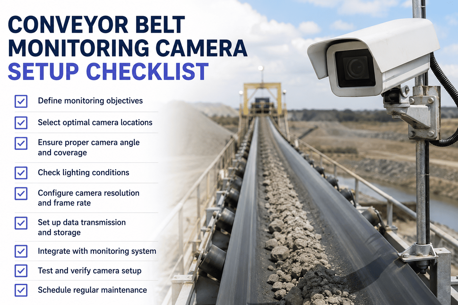
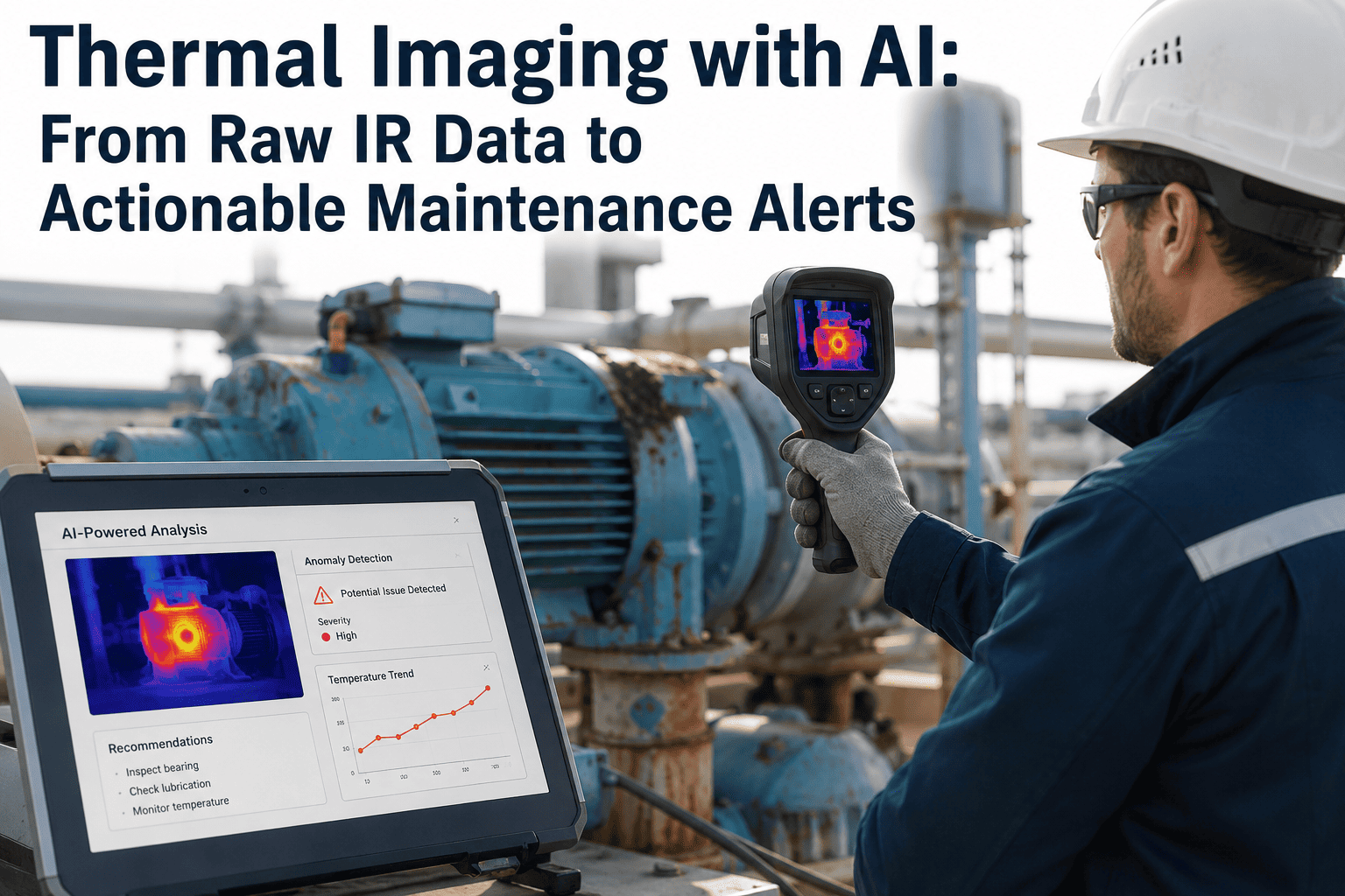
Thermal cameras deliver reliable predictive maintenance value only when installed, calibrated, and verified against measurable optical and environmental parameters — not just mounted and pointed at an asset. A camera reporting a bearing at 82°C when the true surface is 96°C is false confidence, not a diagnostic tool. This checklist walks reliability engineers and Level I–III thermographers through every calibration and verification step a production-grade deployment must satisfy. To see the workflow on your inventory, Book a Demo.
±2°C
Absolute measurement accuracy after calibration
<30 mK
NETD threshold for industrial condition monitoring
0.10 to 0.98
Emissivity range configured per material
6-8 weeks
Time from install to first predictive alert
Deploy Calibrated Thermal Monitoring Across Every Critical Asset — Automated Emissivity and NETD Verification Built In
iFactory ingests FLIR, Fluke, and Optris feeds, applies emissivity libraries, and generates baseline-referenced anomaly alerts within hours.
Book a Demo to see the workflow on your assets.
Why Uncalibrated Cameras Are Worse Than No Program at All
A miscalibrated camera does not produce less accurate data — it produces confidently wrong data planners act on as reliable. A coupling at 118°C reported as 94°C because emissivity was left at 0.95 for polished aluminium passes every CMMS threshold check, and still fails unexpectedly. The calibration burden is real but bounded — emissivity libraries persist, reflected temperature updates from ambient feeds, and NETD verification is quarterly. Programs generating five-figure annualised savings differ from those producing false alarms only in whether these checklist steps were completed before the first thermogram was trusted.
Section 1: Pre-Installation Site Assessment Checklist
Every installation begins with a site assessment covering mounting, cable routing, ambient exposure, and detector geometry. Skipping this step is the most common cause of programs that never reach production reliability.
Target Asset and Line-of-Sight Verification
Direct line-of-sight to target confirmed — no intervening glass, plastic, or mesh
Standard glass blocks over 90% of IR in the 7-14 µm band. Polycarbonate guards or safety mesh in the path invalidate the reading — the camera measures the guard, not the asset.
Target-to-detector distance measured for spot size calculation
The IFOV must resolve the smallest feature. A 320×240 detector at 3m may not resolve a 12mm terminal lug.
Angle of incidence below 30 degrees from surface normal
Emissivity is angle-dependent. Beyond 30 degrees off-normal, apparent emissivity drops sharply — an error emissivity setting cannot fix. Reposition or accept the penalty.
Ambient temperature range and dust/steam exposure characterised
Housing IP and operating limits are set by environment, not datasheet default. Undersized enclosures cause first-year failures.
Section 2: Camera Mounting and Field-of-View Configuration
Physical mounting sets geometric constraints on every thermogram. A camera on a vibrating structure or obstructed view produces untrustworthy readings.
01
Vibration-isolated mounting bracket installed
Mounting must be structurally independent from the asset. Isolation pads for local vibration prevent motion-blurred thermograms.
02
Field-of-view mapped to inspection zones
Define measurement regions — housing, bearing, coupling, terminal box — with margin for expansion under load.
03
Focus locked at operational target distance
Manual focus set on a high-contrast feature and physically locked. Auto-focus drifts and is unsuitable.
04
Reference emissivity target installed in frame
A known-emissivity surface in the field of view enables drift verification between quarterly checks.
05
Cable routing, ingress sealing, power redundancy
Cables sealed against dust and moisture at every penetration. UPS on safety-critical assets.
Section 3: Emissivity and Reflected Temperature Compensation
Emissivity and reflected temperature produce the largest errors when defaulted. Correctly set, readings come within ±2°C of thermocouple reference. Defaulted, errors on reflective surfaces exceed 20°C.
Reflected Temperature Compensation Configuration
Reflected apparent temperature measured, not assumed
Use crumpled matte aluminium foil at target position, read at emissivity 1.0. Never assume the value equals room temperature.
Compensation re-verified for enclosed asset environments
Cameras near furnaces or in heated enclosures need reflected temperatures 20-40°C above ambient. Failing to re-verify overestimates readings on reflective busbars.
Emissivity library persisted per camera and per region of interest
Global camera-level emissivity fails for multi-material scenes. A frame with a painted motor and copper busbar needs 0.94 and 0.15 on the correct pixels.
Section 4: NETD and Measurement Range Verification
NETD and measurement range determine whether the camera can resolve the differences your inspection looks for. A 100 mK NETD camera cannot detect a 0.5°C bearing rise against ambient noise regardless of emissivity setting.
Detector
NETD verified below 30 mK at reference temperature
Confirm published NETD against a controlled blackbody at 30°C. Cameras above 50 mK are unfit for tight-tolerance work.
Range
Measurement range spans expected thermal envelope with margin
Range covers minimum ambient through maximum fault — typically ambient minus 20°C to 200°C for electrical. Disable auto-ranging on fixed cameras.
Uniformity
Non-uniformity correction executed and validated
Uniform-source imaging verifies pixel consistency. NUC drift signals window contamination or detector degradation.
Reference
Contact thermocouple cross-validation at three temperature points
Compare K-type or T-type readings against the camera at three temperatures. Deviation over ±2°C triggers recalibration before sign-off.
Response
Frame rate matched to inspection application
Rotating machinery and arcing need higher frame rates than static equipment. 1 Hz misses arcing.
Drift
Quarterly drift check scheduled against reference standard
Uncooled microbolometers drift with age. Quarterly comparison against a portable blackbody predicts factory recalibration needs before drift causes missed detections.
Section 5: Environmental Compensation and Ambient Conditions
Humidity, air temperature, window transmissivity, and airflow all modify the signal path. These must be explicitly compensated, not assumed to cancel.
Atmospheric and Optical Path Compensation
Ambient temperature and humidity ingested from sensor feeds
Humidity above 60% at over 5m produces measurable atmospheric absorption. Connect to weather or HVAC feeds — manual entry is unreliable for continuous monitoring.
Germanium window transmissivity documented and cleaned monthly
Protective windows have transmissivity typically 0.85 to 0.98. Configure this in camera parameters. Dust, oil, and steam degrade it — schedule monthly cleaning.
Solar loading identified for outdoor installations
Outdoor cameras in direct sun show apparent temperatures varying with sun angle and cloud. Shade shields, tracking profiles, or night-only windows are the mitigations.
Convective airflow characterised for near-fan and outdoor installs
Airflow across a heated surface lowers measured temperature versus still air. Baseline under representative airflow — not still-air commissioning.
Section 6: Baseline Thermal Capture and Reference Documentation
The baseline is the reference every inspection is compared against. A baseline on a lightly loaded motor at 20°C triggers false alerts every summer at 32°C ambient.
A
Capture under representative full-load operating condition
Asset at typical load for two hours before capture — sufficient for steady state. Startup or idle captures produce misleading thresholds.
B
Simultaneous ambient reference for delta-T calculation
Ambient captured with each baseline. Delta-T detection compensates seasonal variation that otherwise generates spurious alerts.
C
Document capture conditions in the CMMS
Load, ambient, humidity, elapsed time, and recent maintenance recorded with the baseline. Without context it is a photograph, not a reference.
D
Build seasonal and load-condition baseline library
Single baselines generate false alarms across the envelope. Capture three load conditions and two seasonal extremes — the library supports year-round detection without retuning.
E
Sign-off by Level II or Level III certified thermographer
ASNT SNT-TC-1A requires thermographic procedures be reviewed by a certified thermographer. Sign-off provides the audit trail insurance reviews require.
Section 7: Alert Configuration and CMMS Integration
A calibrated camera whose thermograms no planner sees delivers zero value. CMMS and alert workflow integration converts monitoring from data collection into a maintenance program.
CMMS and Alert Workflow Integration
Anomaly thresholds configured per asset criticality tier
Delta-T thresholds per NETA MTS-2019 — typically 10°C advisory, 25°C planned action, 40°C immediate. Rotating machinery follows ISO 18434 severity.
Work order auto-generation for advisory and action anomalies
Each breach creates a CMMS work order with the annotated thermogram. Manual re-entry undermines otherwise well-run programs.
Trend dashboard configured for slow-developing anomalies
Some failures develop over weeks. A bearing 3°C above baseline trending 1°C per week is a predictive signal single-frame alerts miss.
Escalation paths mapped to on-shift maintenance responsibility
Alerts routed to the correct on-shift responder — not a generic mailbox. Escalation to reliability engineering for unacknowledged critical alerts.
Documented Thermal Program Outcomes
Fully calibrated thermal programs generate five- to seven-figure annual savings by catching electrical faults and bearing failures weeks before downtime.
70-90%
Reduction in unplanned downtime
4-8 weeks
Advance warning between anomaly and failure
3-5x
First-year ROI in reactive facilities
Frequently Asked Questions About Thermal Camera Installation and Calibration
How often does a fixed-mount thermal camera need to be recalibrated after commissioning?
Emissivity and reflected temperature persist and do not require recalibration unless the target surface changes — for example, if a painted motor is repainted. NETD verification and NUC should be checked quarterly against a reference blackbody. Factory recalibration is typically every two years for uncooled microbolometers, sooner if drift exceeds ±2°C. iFactory automates the quarterly drift check, and
our engineering team can walk through the schedule for your detector.
What emissivity value should be used for polished copper busbars in electrical switchgear?
Polished copper has emissivity between 0.05 and 0.15 in the long-wave IR band, making direct measurement unreliable — the camera reads reflected ambient energy, not surface temperature. Apply a dot of high-emissivity paint or PVC tape to a non-current-carrying region and measure that dot at emissivity 0.95. This gives a reliable reference from which busbar temperature is inferred through thermal conductivity.
Book a Demo to see the workflow across a switchgear lineup.
Can a thermal camera measure through a viewing window in an electrical panel?
Only through IR-transparent windows designed for thermographic inspection — calcium fluoride, zinc selenide, or specialised polymer with published transmissivity in the 7-14 µm band. Standard glass, polycarbonate, and acrylic block over 90% of long-wave IR and produce meaningless readings. Window transmissivity must be configured in camera parameters, and the window kept clean since dust and oil degrade transmissivity. If unsure whether your windows are IR-rated,
contact our engineering team.
What NETD is appropriate for condition monitoring of electrical connections and rotating machinery?
Industrial condition monitoring requires detectors with NETD at or below 30 mK at 30°C reference. Above 50 mK the noise floor obscures small differences indicating early bearing wear, connection resistance increases, and lubrication degradation. Higher NETD detectors work for gross fault detection at 20°C above ambient but cannot support the tight-tolerance trend analysis that generates weeks of advance warning. iFactory supports cameras with NETD from 20-40 mK —
Book a Demo covers detector selection.
How does iFactory reduce the manual burden of emissivity configuration across dozens of cameras?
The platform maintains a material-property library keyed to asset type — motor housing, copper busbar, stainless piping — and applies the appropriate emissivity to each region of interest within the frame. Reflected temperature is fed continuously from ambient sensors, and delta-T detection references per-asset baselines that adapt to seasonal variation. This eliminates the manual configuration burden that has historically limited thermal monitoring to a handful of critical assets.
Book a Demo to see it running against your inventory.
Turn Thermal Cameras Into a Production-Grade Predictive Program — Not Just an Inspection Tool
iFactory automates emissivity libraries, reflected temperature compensation, NETD verification, baseline capture, and CMMS integration across your fixed-mount inventory — a facility-wide capability with ±2°C accuracy.
±2°C accuracy after automated calibration
Material-specific emissivity per region
Quarterly NETD drift check, no bench testing
CMMS work order auto-generation on anomalies