A loose lug on a breaker terminal gives no warning before it fails. It simply gets hotter, cycle after cycle, until insulation degrades and a connection that once carried load safely becomes an arc flash event or a fire. Thermal imaging is the one inspection method that catches this failure mode while it is still a maintenance ticket instead of an incident report — which is why infrared thermography is no longer just a best practice but a mandatory annual requirement under the current NFPA 70B standard for nearly all electrical equipment. Setting a thermal camera up correctly, however, is where most facilities lose the value: wrong mounting angle, no consistent emissivity setting, and no defined threshold for what actually counts as an alarm. Here is exactly how to configure continuous thermal monitoring so it produces trustworthy data instead of noise, and how to book a demo to see it running on your panels.
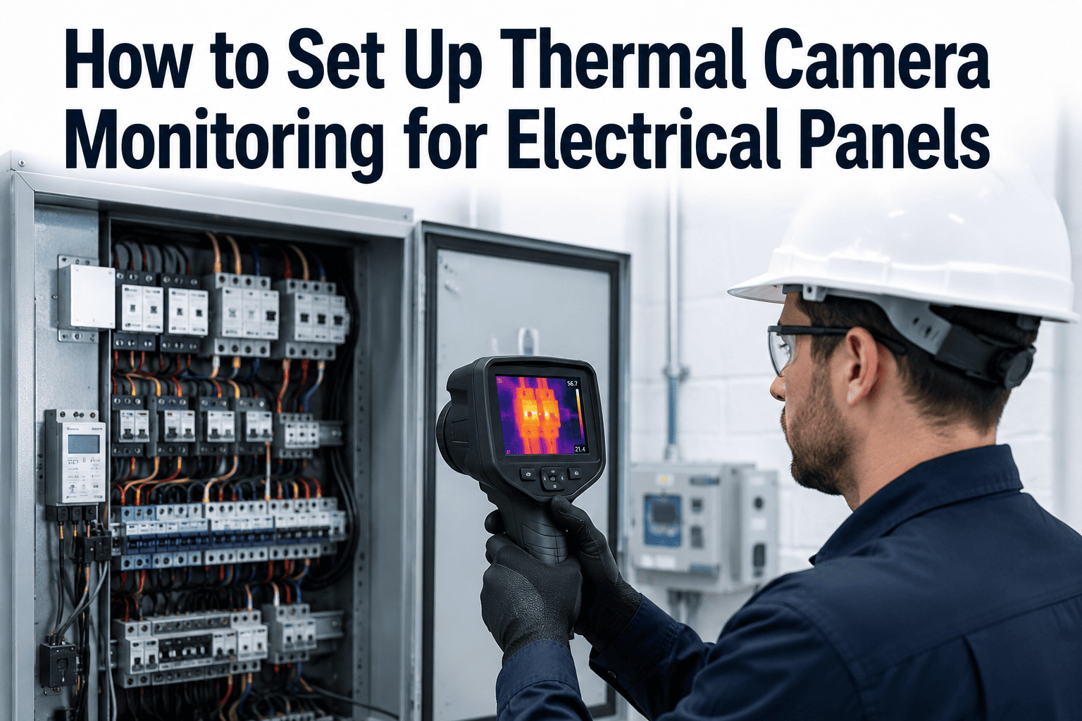
How to Set Up Thermal Camera Monitoring for Electrical Panels
Mounting position, emissivity, alarm thresholds, and CMMS integration — the complete setup sequence for NFPA 70B-aligned continuous thermography
12 Months
Maximum inspection interval for all electrical equipment
6 Months
Required interval for equipment flagged Condition 3
Why Panels Fail Silently Without Thermal Monitoring
Visual inspection and periodic testing catch obvious wear, but a degrading connection radiates heat long before any visible sign appears. Thermal imaging turns that invisible signal into an early warning.
Loose Connections
Vibration and thermal cycling gradually loosen lugs and terminals, increasing resistance and generating localized heat long before visible arcing.
Overloaded Circuits
Load growth beyond original design intent raises operating temperature across a circuit, accelerating insulation breakdown over time.
Imbalanced Phases
Uneven current distribution across phases creates asymmetric heating patterns that a single-point temperature reading would never reveal.
Corrosion & Contamination
Moisture, dust, and corrosion increase contact resistance at connection points, producing a heat signature specific to that failure mode.
The 6-Step Setup Sequence
Getting reliable thermal data is a matter of following a defined sequence, not simply pointing a camera at a panel and recording a number.
Step 1
Mounting Position
Position the camera with a clear, unobstructed line of sight to the target components, ideally perpendicular to the surface to avoid angular measurement error. Fixed-mount cameras on high-risk panels remove the need to open live cabinets repeatedly for manual scans.
Step 2
Define Measurement Zones
Mark specific measurement spots on each breaker, lug, bus bar, and termination point rather than relying on a single wide-frame reading. Each zone should have its own baseline temperature for comparison over time.
Step 3
Configure Emissivity
Set the correct emissivity value for each material surface — painted metal, bare copper, and insulated cable jackets all radiate heat differently. An incorrect emissivity setting is the single most common cause of inaccurate thermal readings.
Step 4
Establish Temperature Thresholds
Compare temperature differences between similar components under similar load, and between each component and ambient air — the delta-T approach specified for compliant thermographic inspection. Set thresholds based on that delta, not an absolute number alone.
Step 5
Set Alarm Rules
Configure escalating alarm tiers — advisory, priority, and urgent — tied to how far a reading exceeds its delta-T threshold, so a minor deviation and a dangerous hotspot never trigger the same response.
Step 6
Integrate with CMMS Work Orders
Route every alarm directly into a maintenance work order with the annotated thermal image attached, so the finding reaches a technician immediately instead of sitting in a report that gets reviewed weeks later.
Getting emissivity and thresholds wrong is the fastest way to a monitoring program nobody trusts. Book a demo to see the configuration walked through on your panel types.
Delta-T Severity Reference
Thermal severity is judged by the temperature rise above a normal reference point, not by a single fixed number across every facility.
| Delta-T Above Reference |
Likely Condition |
Recommended Action |
| 1–3°C |
Within normal operating variation |
Continue routine monitoring schedule |
| 4–15°C |
Developing anomaly, possible minor issue |
Investigate at next scheduled maintenance window |
| 16–40°C |
Probable deficiency requiring attention |
Schedule repair within days, increase monitoring frequency |
| Over 40°C |
Major deficiency, high failure risk |
Immediate correction, consider de-energizing if safe |
Turn Every Hotspot Into a Work Order Automatically
iFactory connects thermal camera alarms directly to your CMMS, so a rising delta-T becomes a scheduled repair before it becomes a shutdown.
Inspection Frequency by Equipment Condition
Under current thermography guidelines, the required inspection interval depends on the documented physical condition of the equipment, not a single blanket schedule for the whole facility.
Condition 1
Equipment with no unresolved findings and maintenance performed on schedule. Standard annual thermographic inspection applies.
Condition 2
Equipment where maintenance results have started to deviate from prior results or manufacturer guidance. Annual inspection continues with closer trend review.
Condition 3
Equipment with missed maintenance cycles, unresolved monitoring alerts, or urgent prior findings. Requires thermographic inspection at least every six months.
Frequently Asked Questions
How often does NFPA 70B require thermal inspections on electrical panels?
Under the current standard, thermographic inspection is required at least every 12 months for essentially all electrical equipment operating under load. Equipment classified as Condition 3 — meaning it has missed maintenance cycles, has an unresolved monitoring alert, or had urgent findings on a prior inspection — must be inspected at least every six months instead. Continuous camera monitoring on high-risk panels effectively exceeds either requirement automatically. Bring your equipment list to a
demo call to map your specific intervals.
What is emissivity and why does getting it wrong ruin the reading?
Emissivity is a measure of how efficiently a surface radiates infrared energy compared to a perfect emitter. Painted metal, bare polished copper, and plastic insulation all have very different emissivity values, and using the wrong setting for a given surface can produce a temperature reading that is off by tens of degrees. Getting this wrong is the single most common reason thermal readings are dismissed as unreliable by maintenance teams.
Should we use handheld cameras or fixed continuous monitoring?
Handheld thermography works for periodic compliance scans on lower-risk equipment, but it only captures a single moment in time and requires a technician to open live panels repeatedly. Fixed continuous monitoring on your highest-risk panels catches developing hotspots between scheduled scans, trends temperature over time automatically, and removes the need for repeated exposure to live components — a meaningful safety benefit on its own.
What temperature difference should actually trigger an alarm?
Rather than a single absolute temperature, compliant thermography compares the temperature of a component against a similar component under similar load, or against ambient air — the delta-T method. A rise of a few degrees may be normal operating variation, while a rise of fifteen degrees or more above that reference point typically signals a developing deficiency that warrants investigation before the next scheduled maintenance window.
Can thermal alarms connect directly into our existing CMMS?
Yes. Thermal camera alarms can be configured to generate a maintenance work order automatically the moment a threshold is exceeded, with the annotated thermal image attached for the technician reviewing the ticket. This closes the loop between detection and correction without relying on someone manually reviewing a report days or weeks after the scan. Contact
support to confirm compatibility with your current CMMS platform.
See Continuous Thermal Monitoring on Your Panels
From mounting position to CMMS-connected alarms, we will map the full setup against your equipment list and your NFPA 70B compliance schedule.