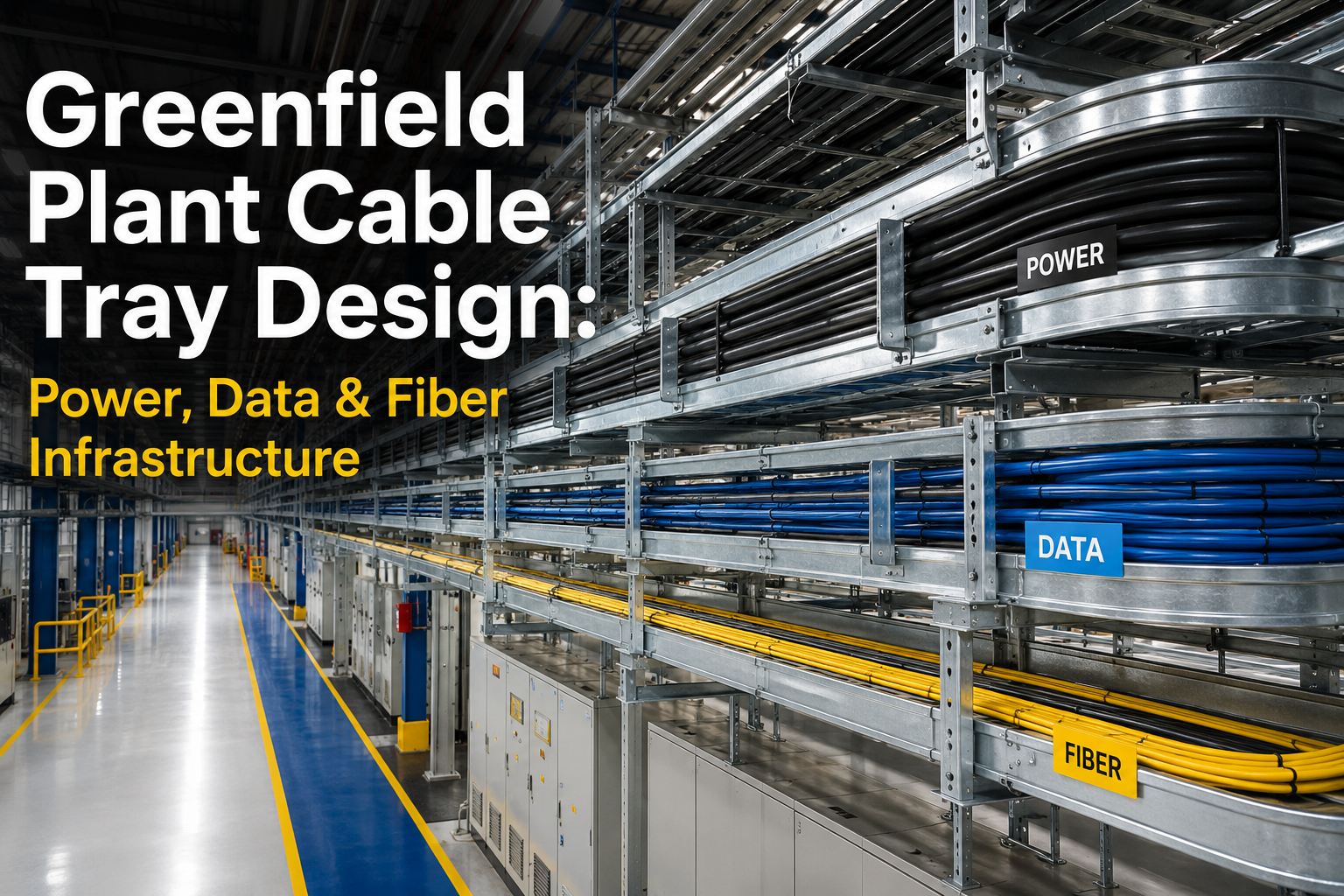
Greenfield Plant Cable Tray Design: Power, Data & Fiber Infrastructur
By Riley Quinn on June 22, 2026
Cable tray design is one of the most under-engineered systems in greenfield plant builds — until commissioning, when undersized trays, missing separation, and absent fiber pathways cost months of retrofit work. NEC 2026 Article 392 brought new clearance rules, refined fill limits, and explicit requirements that separate power, control, and data cabling on every modern industrial installation. The stacked-tray architecture below covers the layout, sizing, segregation, and capacity planning required to deliver an AI-native plant where future cabling additions don't require pulling down the ceiling. Book a cable infrastructure consultation to design the tray architecture before construction drawings are finalised.
The Stacked-Tray Architecture That Separates Power From Signal — and Plans for Year 5
12"Minimum vertical clearance above trays — NEC 2026 update
40% / 50%Max fill — power trays / control trays per NEC 392
2" / 12"NEC minimum / industry best-practice power-to-signal separation
30–50%Spare capacity headroom for future cabling additions
NEC 2026 Article 392: The Rules That Drive Every Cable Tray Decision
NEC 2026 Chapter 7 was reorganised — limited energy rules that previously sat in Article 800 are now distributed across Articles 725, 760, 770, 805, and 820. Article 392 still governs cable tray construction and installation, with new clearance and separation requirements. These six rules drive every tray decision.
R1
12-Inch Vertical Clearance
NEC 2026 update — minimum 12 inches of clear vertical space above trays for installation and maintenance access. Plants that ignore this fail inspection at commissioning.
R2
Fill Limit 40% Power / 50% Control
Power cables max 40% of tray cross-sectional area. Control cables max 50%. Per NEC Table 392.22(A). Exceeding fill limit causes overheating and code violation.
R3
2-Inch Minimum Separation
Power and signal cables in same tray require 2-inch minimum separation or a fixed metallic barrier. Industry best practice is 12+ inches vertical separation.
R4
Support Spacing 6–10 ft
Standard trays require supports every 6 to 10 feet. Heavy-duty long-span trays handle up to 20 ft between supports. Unsupported span at equipment exit ≤6 ft.
R5
Equipment Grounding via Tray
Metallic trays can serve as Equipment Grounding Conductor (EGC) when meeting NEC bonding and sizing requirements. Saves dedicated EGC conductor cost.
R6
VFD Output Cable Shielding
VFD output cables require shielded construction and maximum separation from instrument cables. Common-mode current management critical for control loop stability.
What Goes Where: Cable Type to Tray Tier Mapping
Putting the right cable on the right tier prevents EMI, code violations, and the most common construction-phase rework. The five-tier architecture below is the canonical layout — modify by industry, but never collapse without engineered justification.
Tier 1
Main Power Feeders
MV distribution · 4/0 AWG and larger feeders · Bus tie cables · Generator paralleling
Site WAN fiber · OT-IT backbone · Inter-building runs · Edge compute fiber feed
Fiber immune to EMI · Can share trays
Need the 5-tier architecture sized for your specific plant load? Book a cable infrastructure consultation — we will produce the tray sizing and routing before construction drawings.
Cable Tray Sizing: The Math That Determines Tray Width & Height
Most greenfield projects undersize trays because the sizing calculation looks at day-one cable count, not 5-year capacity. Right-sizing means applying fill limits to the actual cable schedule plus deliberate spare capacity. The 4-step calculation below is what every electrical engineer should run before specifying tray widths.
Step 1
Sum Cable Cross-Sectional Area
For all cables routing through the tray, sum the cross-sectional area (πr²) from cable manufacturer data sheets. Include power, control, instrumentation, network — by tier.
Output: Total cable area in square inches per tier
Step 2
Apply NEC Fill Limit
Divide total cable area by the NEC fill ratio: 40% for power trays, 50% for control trays. This gives the minimum required tray cross-sectional area for code compliance.
Output: Minimum compliant tray area
Step 3
Add 30–50% Spare Capacity
Multiply minimum compliant area by 1.3 to 1.5 for future cable additions. Plants without spare capacity require ceiling teardown and tray replacement when expanding — at 4 to 6× greenfield cost.
Output: Recommended tray area with growth headroom
Step 4
Select Standard Tray Width
Match required area to standard tray widths (6", 9", 12", 18", 24", 30", 36") at standard depth (3", 4", 5", 6"). Standard sizes have shorter lead times and broader supplier availability.
Output: Specified tray width × depth per tier
Get the 5-Tier Architecture Sized for Your Plant Before Construction Drawings
iFactory's cable infrastructure consultation covers tier architecture, NEC 2026 compliance, cable schedule analysis, tray sizing with 30 to 50% spare capacity, support spacing, and fiber backbone routing — delivered before construction drawings are finalised.
Tray Material Selection: Steel, Aluminium, FRP, or Stainless
The wrong tray material drives long-term corrosion, weight overhead, and unexpected replacement costs. Material choice is driven by environment, load, weight constraint, and corrosion exposure — not by procurement preference for the lowest unit cost.
Pre-Galvanised Steel
Standard indoor manufacturing environments
Highest strength-to-cost · Best support spans · Easy to ground
Heavy · Corrodes in wet/chemical exposure
Hot-Dip Galvanised Steel
Outdoor or harsh indoor exposure
Strong corrosion protection · Reasonable cost · Long life
No corrosion · Non-conductive · Excellent in harsh atmospheres
Requires separate EGC · Limited fire ratings · Higher cost
Expert Perspective: Why Plants Pay 4–6× More to Retrofit Cable Trays After Year 3
The cable trays we audit at year 3 of plant operation almost always need expansion — and almost always weren't designed for it. AI-native plants add sensors, IoT devices, fiber backbone runs, and edge compute connections continuously. Trays sized for day-one cable count run out of capacity within 24 to 36 months. Retrofitting trays in an operating plant means dropped ceilings, production interruption, and 4 to 6 times the greenfield cost per linear foot. The fix is 30 to 50% spare capacity designed in at FEED — typically adding 5 to 10% to electrical CapEx and preventing the inevitable retrofit project.
— iFactory Greenfield Consulting, Electrical Infrastructure Practice 2025 to 2026
4–6×
Retrofit cost vs. greenfield specification per linear foot
24–36 mo
Typical time until day-one-sized trays hit capacity
5–10%
CapEx premium for designed-in spare capacity at FEED
Ready to design tray capacity for year 5 — not just day one? Talk to our cable infrastructure team — we will size the tray architecture for AI-native growth.
Design Cable Trays for Year 5 Growth — Not Just Day-One Cable Count
iFactory's cable infrastructure consultation covers the 5-tier tray architecture, NEC 2026 compliance, fill calculation with 30 to 50% spare capacity, material selection by environment, support spacing, fiber backbone integration, and AI-native infrastructure provisioning — all delivered before construction drawings are finalised.
NEC 2026 introduced a 12-inch minimum vertical clearance above cable trays for installation and maintenance access — previously not explicitly required. Chapter 7 was also reorganised, distributing limited energy rules across Articles 725, 760, 770, 805, and 820 instead of the previous Article 800. Fill limits, support spacing, and separation rules remain consistent with prior NEC editions but now reference the updated Chapter 7 structure.
Can fiber optic cables share trays with power cables?
Yes. Fiber optic cables are immune to EMI and can be installed in power cable trays without separation concerns. This is one reason fiber is increasingly preferred for industrial communication backbone runs where cable trays are shared. However, mechanical protection and bend radius requirements still apply, and most modern designs still place fiber on dedicated tiers for organisation and future expansion.
What is the actual fill limit for cable trays under NEC 392?
For power cables in ladder or ventilated trough trays, total fill cannot exceed 40% of the tray's cross-sectional area per NEC Table 392.22(A). For control cables, the limit is 50%. Cables larger than 4/0 AWG must be installed in a single layer with cable diameters summing to no more than the tray width. Solid-bottom trays have reduced fill limits.
How much spare capacity should be designed into greenfield cable trays?
Industry best practice is 30 to 50% spare capacity above day-one cable count. AI-native plants add sensors, edge compute connections, and fiber runs continuously — typical day-one-sized trays hit capacity within 24 to 36 months. Designed-in spare capacity costs 5 to 10% premium on electrical CapEx but prevents retrofit projects that cost 4 to 6 times more per linear foot in operating plants.
How does iFactory's cable infrastructure consultation work?
iFactory's consultation covers the 5-tier tray architecture, NEC 2026 Article 392 compliance review, cable schedule analysis with fill calculation, tray sizing with 30 to 50% spare capacity, material selection by environment, support spacing per load class, fiber backbone integration, and AI-native infrastructure provisioning. All outputs are delivered before construction drawings are finalised. Book your consultation here.