AI-Ready Electrical Infrastructure Design for Greenfield Manufacturing Facilities
By Riley Quinn on June 9, 2026
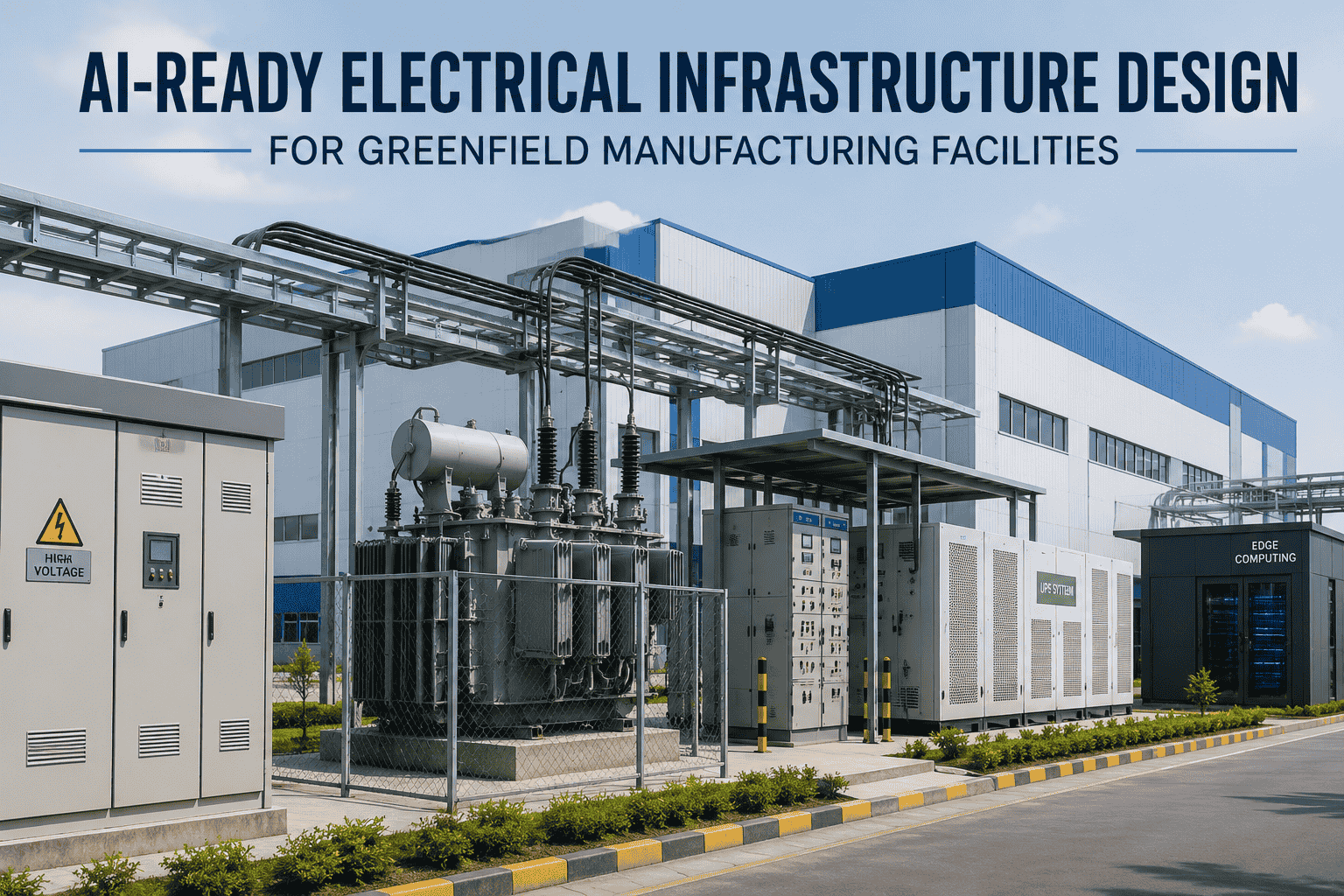
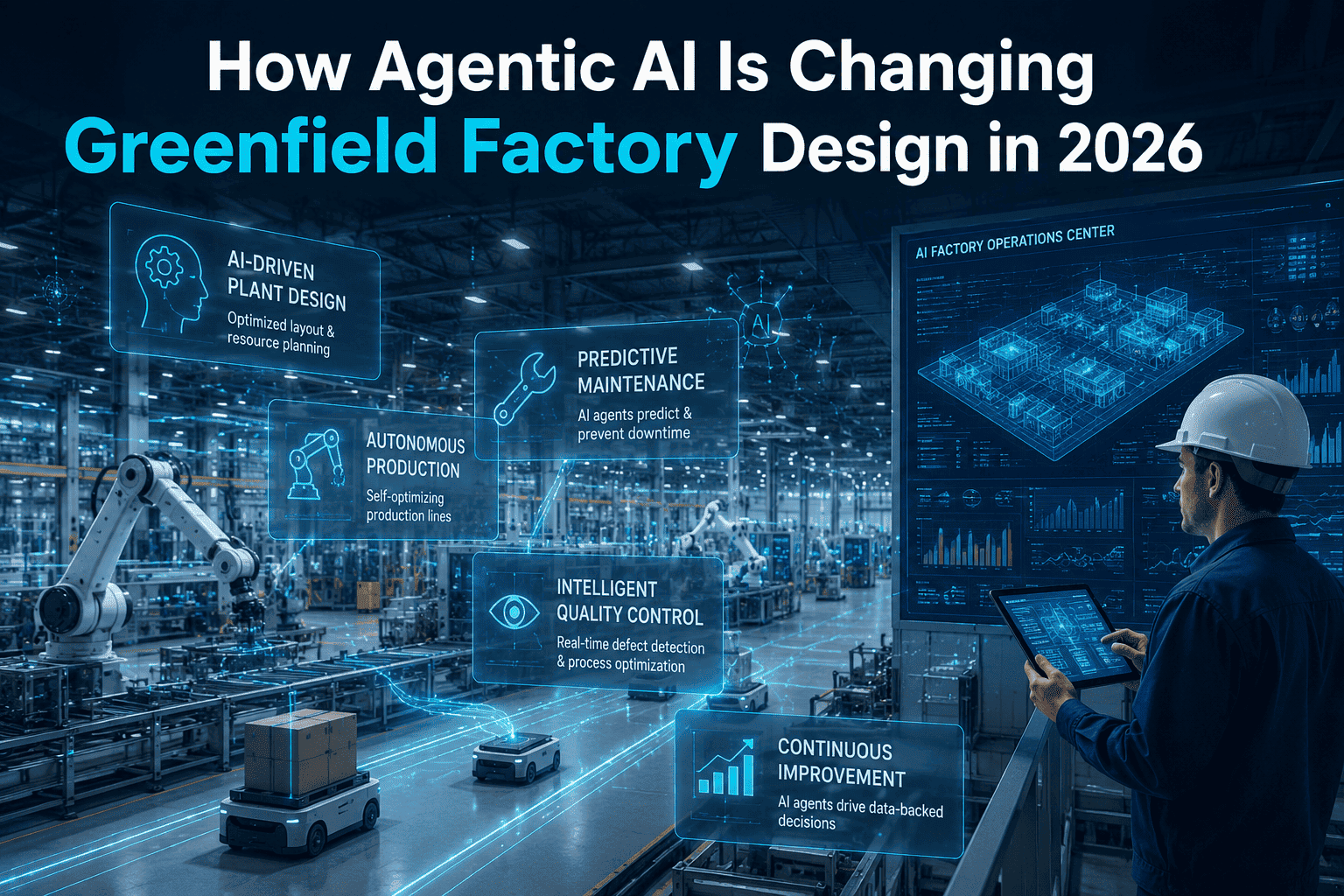
Most greenfield manufacturing facilities are engineered meticulously—production lines, material flow, fire protection, safety systems. Then the electrical infrastructure for AI and edge computing gets treated as a Phase 2 afterthought. By the time commissioning starts, the gaps are painfully visible: undersized transformers, no conditioned power for edge servers, a single-feed substation with zero redundancy, and a utility interconnect that can't grow with AI workloads. Retrofitting electrical infrastructure after walls go up costs three to five times more than designing it right the first time. This guide covers exactly what AI-ready electrical design looks like in a greenfield manufacturing facility—before the first shovel breaks ground.
The AI Power Gap in Greenfield Manufacturing
Traditional factory electrical design was built for motors and lighting. AI-ready infrastructure demands a fundamentally different approach.
Conventional Electrical Design
Single utility feed with basic ATS switchover
Lighting + motor loads only — predictable, stable draw
No conditioned power zones for computing
Manual load management, no telemetry
UPS sized for IT closet, not edge compute racks
AI-Ready Electrical Design
Dual-feed medium-voltage with N+1 transformer redundancy
Dynamic, spiky AI/edge loads — fast transient tolerance required
Dedicated conditioned power zones for edge + AI racks
Smart meters, SCADA-integrated load telemetry
Industrial UPS with AI load profile simulation
The Five-Layer Electrical Architecture for AI-Ready Factories
Designing power infrastructure for a greenfield factory that runs AI and edge computing systems requires thinking in layers—from the utility interconnect down to the rack. Each layer has distinct requirements, failure modes, and sizing rules. Skipping or under-specifying any layer creates a bottleneck that surfaces during commissioning or, worse, during production ramp-up.
L1
Utility Interconnect & Substation
Your power foundation — get this wrong and nothing else can fix it
Grid Entry
Secure dedicated medium-voltage (12–34.5 kV) service with utility interconnect agreements locked before site selection. Size for 125–150% of Day 1 load to accommodate AI workload growth. Plan for dual feeds from separate substations where possible. New utility connections face 2–5 year lead times in capacity-constrained regions.
Medium Voltage ServiceDual-Feed RedundancyFuture Load Headroom
L2
Main Switchgear & Transformer Bank
The distribution hub — sized for AI density, not just production motors
HV Distribution
Deploy dry-type or liquid-filled transformers with N+1 redundancy for critical loads. Intelligent switchgear with IEC 61850 communication integrates with your facility SCADA for real-time load visibility. Separate transformer banks for production OT loads and IT/AI loads prevent harmonic interference from variable-frequency drives corrupting edge computing power.
Where production and AI power paths diverge — must be segregated
LV Distribution
Dedicated low-voltage distribution panels for AI and edge compute, isolated from variable-frequency drive (VFD) circuits. Install power quality monitoring at panel level to detect harmonics, voltage sags, and flicker. Active harmonic filters protect sensitive edge server power supplies from motor-start transients. IEEE 519-2022 compliance targets: THD <5% at the point of common coupling.
The bridge between utility power and AI compute reliability
Power Conditioning
Size industrial UPS systems against actual AI load profiles—not legacy IT assumptions. AI workloads spike to 120–130% of nominal during training bursts then drop sharply; UPS must tolerate these fast transients without false transfer to bypass. Double-conversion online UPS architecture provides complete isolation from grid disturbances. Battery runtime: minimum 15 minutes for orderly shutdown of edge AI systems plus generator transfer time.
Intelligent PDUs with per-outlet metering feed edge AI servers. Plan for 8–15 kW per edge rack for inference workloads; heavy AI training racks can exceed 30 kW. Deploy rack-level remote power monitoring integrated with the facility energy management system. Future-proof conduit and busway sizing to support density upgrades without civil works.
Unsure how to size your electrical infrastructure for AI workloads? Book a Greenfield Consultation — iFactory's engineers model your full power architecture before a single design drawing is finalized.
Power Demand Benchmarks: What AI Actually Draws in a Manufacturing Facility
The biggest mistake in greenfield electrical design is applying data-center-style assumptions to manufacturing environments, or worse, applying legacy factory assumptions to AI workloads. Real manufacturing AI deployments have a distinct load profile. Use these benchmarks as your sizing baseline.
System / Load
Typical Draw
Load Behavior
UPS Required
Edge AI Inference Server (per rack)
6–15 kW
Moderate, cyclic spikes during inference
Yes — Mission Critical
AI Vision / Quality Inspection System
4–10 kW
High-frequency bursts during inspection cycles
Yes — Mission Critical
Predictive Maintenance Edge Node
2–6 kW
Steady-state baseline, low variability
Yes — Mission Critical
SCADA / MES / Historian Servers
3–8 kW
Sustained steady load, moderate spikes
Yes — Mission Critical
Production Motor Loads (per line)
50–500 kW
High inrush on start, steady run current
Separate Circuit
HVAC / Cooling Plant
100–800 kW
VFD-driven, heavy harmonic generation
Separate Circuit
Key sizing rule: Total AI and edge compute loads typically represent only 5–15% of a factory's total electrical demand—but they are the most sensitive and highest-consequence loads. Designing separate conditioned circuits for these systems costs a fraction of a single unplanned downtime event.
Smart Grid Integration: Real-Time Power Intelligence
A modern greenfield factory shouldn't just consume power—it should actively manage it. Smart grid integration turns your electrical infrastructure into an intelligent system that responds to tariff signals, shifts deferrable loads, and provides real-time visibility from the utility meter down to individual edge racks. This isn't a luxury feature; in regions where demand charges represent 30–40% of an industrial bill, smart load management pays back in months.
Demand Response Integration
Pre-program deferrable loads—non-critical conveyor systems, HVAC setpoints, compressed air—to shed automatically when utility sends a DR event signal. A well-configured demand response program can trim 10–20% of peak demand, directly reducing demand charges without impacting production throughput.
10–20% peak demand reduction
Time-of-Use Tariff Optimization
Integrate utility tariff schedules into the facility energy management system (FEMS). Shift energy-intensive batch operations—heat treatment, large compressor cycles—to off-peak windows. For AI training workloads that can tolerate scheduling, time-shifting model retraining jobs to overnight off-peak hours can cut electricity costs by 25–35% for those loads.
25–35% cost reduction on shiftable AI loads
Energy Storage & Microgrid Capability
Battery energy storage systems (BESS) sized at 15–30 minutes of critical AI and production load capacity serve double duty: they buffer transient demand spikes (protecting transformers from AI load cycling) and provide ride-through during grid events. Microgrid-capable facilities with on-site solar or combined heat and power (CHP) can island within 5–10 seconds of a grid fault.
5–10 sec islanding capability
Sub-Metering & Power Analytics
Deploy Class 1 revenue-grade sub-meters at every distribution panel feeding AI and production loads. Sub-meter data feeds your facility's digital twin for real-time PUE tracking, anomaly detection, and load forecasting. When a predictive maintenance AI model flags an anomaly, cross-referencing it against real-time power draw data reveals whether it's a mechanical issue or a power quality event causing the fault signature.
UPS System Design for AI Workloads: What's Different
Traditional manufacturing facilities sized UPS systems for PLC controllers, HMI panels, and small server rooms—loads measured in kilowatts with predictable, stable draw. AI inference and edge computing workloads behave fundamentally differently: they spike sharply during inference bursts, sustain high loads during model execution, then drop to standby. Standard UPS platforms sized by static load calculations fail under these dynamic AI profiles.
Legacy UPS Approach
AI-Ready UPS Design
Sizing Method
Peak nameplate + 20% buffer
AI load profile simulation with burst tolerance
Topology
Line-interactive or standby (offline)
Double-conversion online — full isolation at all times
Load Transient Response
2–10ms transfer gap on switching
Zero transfer — inverter always in path
Battery Chemistry
VRLA lead-acid, fixed runtime
Lithium-ion with 3x cycle life and scalable runtime
Load Management
Manual bypass only
Intelligent load shedding with AI priority tiers
Monitoring Integration
Local panel only, SNMP if lucky
Full SCADA/DCIM integration with predictive battery health
Typical Runtime at AI Load
3–5 min (undersized for actual draw)
15–30 min minimum; generator-transfer compliant
Design Your AI-Ready Power Infrastructure Before Ground Breaks
iFactory's greenfield consulting team models your complete electrical architecture — from utility interconnect to edge rack — in a digital twin before a single design document is signed. Catch undersizing, redundancy gaps, and power quality risks at the design stage, not during commissioning.
Future-Ready Utility Planning: The 10-Year Electrical Roadmap
A greenfield factory built today will likely see two or three generations of AI hardware within its first decade of operation. AI compute density doubles roughly every two to three years. Electrical infrastructure built to today's spec without expansion headroom forces costly civil work—new transformer pads, new conduit runs, new switchgear installations—when AI upgrades arrive. Building in structured expansion is far cheaper than retrofitting.
Year 0–1
Commission & Baseline
Establish sub-meter baseline for all loads
Validate AI load profiles match design assumptions
Commission FEMS (Facility Energy Management System)
Document spare transformer and switchgear capacity
Year 2–4
AI Scale-Up
Deploy additional edge AI racks into pre-wired zones
Expand UPS bank using modular battery cabinets
Add BESS if demand charges are climbing
Review utility capacity with growth in AI inference loads
Year 5–7
Smart Grid & Renewable Integration
Integrate on-site solar or CHP into facility microgrid
Activate demand response programs with utility
Upgrade intelligent PDUs for next-gen AI hardware density
Complete IEC 61850 retrofit on remaining legacy switchgear
Year 8–10
Next-Gen AI Density
Activate pre-installed conduit for 30+ kW density AI racks
Expand substation or add second transformer pad as needed
Evaluate direct DC distribution (48V or higher) for AI zones
Re-baseline FEMS models against decade of operational data
"The single most common and expensive mistake in greenfield industrial projects is treating the electrical system as a commodity—something you specify at the end, sized to what you know today. AI changes that calculus entirely. A transformer bank that looks adequate at commissioning can be a hard ceiling within three years. Build in redundancy, separate your AI power paths from your motor circuits, and commission a FEMS before you commission the first production line."
— Industrial Electrical Infrastructure Design Best Practice, 2025
3–5×
Cost to retrofit electrical vs. designing it right at greenfield
26%
Projected US peak electricity demand growth by 2035
2–5 yr
Lead time for new utility interconnect in constrained regions
Conclusion: Electrical Infrastructure is Your AI Bottleneck—or Your Competitive Advantage
Every AI application your factory deploys—predictive maintenance, AI-driven quality inspection, real-time OEE analytics, digital twin synchronization—runs on electrons. The electrical infrastructure you design today is either the foundation that enables all of it or the constraint that limits it. Getting this right in a greenfield project means specifying dual-feed utility service, separating AI power paths from motor circuits, sizing UPS systems against real AI load profiles, installing smart metering from day one, and building in the conduit headroom for the compute density you'll need in year five and year ten. iFactory's greenfield consulting team validates your complete electrical architecture in a digital twin before design freeze—catching undersizing, redundancy gaps, and power quality risks while they're still lines on a drawing, not problems in the field.
Get Your Greenfield Electrical Architecture Validated
iFactory models your complete power distribution, UPS, smart grid, and edge compute electrical design in a digital twin—before construction starts. Zero costly commissioning surprises. Zero undersized infrastructure.
What makes electrical infrastructure "AI-ready" in a manufacturing facility?
AI-ready electrical infrastructure goes beyond standard factory power design in four key ways: it segregates AI and edge compute loads onto dedicated conditioned circuits isolated from noisy motor and VFD circuits; it deploys double-conversion UPS systems sized against actual AI load profiles rather than static nameplate values; it installs intelligent sub-metering and a Facility Energy Management System (FEMS) for real-time load visibility; and it builds in 25–50% capacity headroom with pre-installed conduit and busway routes to support the compute density growth expected within 5–10 years. Designing these elements at the greenfield stage costs a fraction of retrofitting them into an operating facility.
How much power does an edge AI system require in a typical manufacturing plant?
Power requirements vary by AI application. A predictive maintenance edge node typically draws 2–6 kW. An AI vision and quality inspection system runs 4–10 kW. A full edge AI inference server rack draws 6–15 kW. These loads are individually modest but are highly sensitive to power quality—voltage sags, harmonic distortion, and transients that motor-dominated factory circuits generate routinely can cause GPU throttling, false fault signals, or server restarts. The critical design requirement is not total wattage but power quality isolation: dedicated UPS-backed circuits, active harmonic filtering, and segregated distribution panels.
Why is UPS design different for AI workloads compared to traditional industrial UPS applications?
Traditional industrial UPS systems were sized for stable, predictable loads—PLC controllers, HMI panels, small server rooms—using static load calculations. AI workloads have a fundamentally different profile: they spike sharply to 120–130% of nominal during inference bursts, cycle rapidly between high-compute and standby states, and require zero-transfer protection at all times (not just during utility outages). Standard line-interactive or standby UPS topologies introduce 2–10ms transfer gaps that can reset AI inference engines mid-cycle. Double-conversion online UPS architecture eliminates this by keeping the inverter permanently in the load path. Additionally, AI-load runtime requirements are driven by generator transfer time (typically 10–15 seconds) plus a margin for orderly AI process shutdown—a minimum of 15 minutes at full AI load is the industry design floor.
What is smart grid integration and is it worth implementing in a greenfield factory?
Smart grid integration connects your facility's internal energy management system (FEMS) to utility demand response programs, real-time tariff signals, and automated load control systems. For manufacturing facilities, the primary ROI comes from three areas: demand response programs that shed deferrable loads during utility peak events (reducing demand charges by 10–20%), time-of-use optimization that shifts batch and AI training workloads to off-peak electricity windows (saving 25–35% on those loads), and battery energy storage buffering that reduces transformer stress from AI load cycling. For facilities with demand charges representing 30–40% of the electricity bill—typical for medium-to-large industrial customers—smart grid features pay back within 18–36 months of commissioning.
How early in the greenfield design process should electrical infrastructure for AI be specified?
Electrical infrastructure decisions must be locked in at the site selection and conceptual design phase—before civil and structural drawings are finalized. The reason is cascade dependency: utility interconnect lead times (2–5 years in constrained regions) dictate when you can take power; substation and transformer pad locations drive civil foundation designs; conduit routing is embedded in slab pours; and transformer sizing determines every downstream panel, UPS, and rack power budget. The most expensive scenario is discovering an electrical capacity limitation after walls are up and equipment is ordered. iFactory's greenfield consulting process validates the full five-layer electrical architecture in a digital twin at the conceptual design stage—typically 18–36 months before commissioning—when changes cost design hours, not construction dollars.