CAT6 delivers 1 Gbps up to 100 meters — beyond that, signal degrades and data errors mount. CAT6A pushes to 10 Gbps at the same distance. Fiber optic handles 10-100 Gbps across kilometers with zero EMI interference. Choosing the wrong cable type for even one run means re-pulling — at $50-$150 per meter in a finished facility. Inadequate cable tray sizing means installing new trays over finished floors and ceilings. Wrong environmental ratings mean cables degrade within months in oil, heat, or chemical exposure. Every one of these problems is 100% preventable with greenfield cabling design. We map every cable run before trenching — type, routing, tray sizing, switch placement, termination point — so your network infrastructure works perfectly from day one and contractors bid accurately from a complete cable schedule. Plan Your Cable Infrastructure
The Cost of Getting Cables Wrong
Wrong Cable Type
Installing CAT6 where CAT6A is needed limits you to 1 Gbps — fine for PLCs, but AI vision cameras need 10 GbE. Re-pulling thousands of meters of cable through sealed trays costs $50-$150/m (cable + labor + disruption). A 500m re-pull: $25K-$75K per incident. Greenfield fix: specify cable type per run based on bandwidth requirements, not lowest cost.
$25K-$75K per re-pull incidentUndersized Cable Trays
Cable trays filled to capacity on day one leave zero room for future expansion. Adding IoT sensors, additional cameras, or new production lines means installing new trays over finished ceilings and floors — at 3-5x the cost of correctly sized trays during construction. Greenfield fix: size trays for 40-50% future fill capacity from day one.
3-5x cost to add trays after constructionWrong Environmental Rating
Standard PVC-jacketed cable in an area with cutting oil, hydraulic fluid, or wash-down chemicals degrades within 6-12 months. Industrial-rated cable (oil-resistant, LSZH, or Teflon jacket) costs 20-40% more upfront but lasts 15-20 years. Greenfield fix: specify environmental ratings per zone based on the actual factory environment.
Full cable replacement in 6-12 monthsShared Trays: Signal vs Power
Running data cables alongside VFD power cables in the same tray introduces electromagnetic interference that corrupts sensor data and causes network errors. TIA-568 requires minimum 300mm separation between power and data. Greenfield fix: dedicated data cable trays specified on architectural drawings, physically separated from power routing.
Chronic network errors; impossible to diagnoseWant every cable run correctly specified before construction? Plan Your Cable Infrastructure — we deliver cable schedules, tray sizing, and switch placement as construction-ready documentation.
Cable Selection Matrix: Which Cable Where
| Application | Cable Type | Speed | Max Distance | Shielding | Jacket | Est. Cost/m |
|---|---|---|---|---|---|---|
| PLC / HMI / SCADA | CAT6A S/FTP | 1-10 Gbps | 90m horizontal + 10m patch | Individually shielded pairs + overall foil | Industrial LSZH or PVC oil-resistant | $0.80-$1.50 |
| AI Vision Cameras | CAT6A S/FTP or OM4 Fiber | 1-10 Gbps per camera | 100m (copper); 400m (fiber) | S/FTP for copper; N/A for fiber (EMI immune) | Industrial; fiber in innerduct for protection | $0.80-$1.50 (Cu); $0.70-$1.50 (fiber) |
| Building Backbone | OM4 Multimode Fiber | 10-100 Gbps | 150m (100G); 400m (10G) | N/A (fiber is inherently EMI-immune) | Riser (OFNR) or Plenum (OFNP) | $0.70-$1.50 |
| Campus / Building-to-Building | OS2 Singlemode Fiber | 10-100+ Gbps | 10+ km | N/A | Armored for direct burial or aerial | $0.40-$0.80 (+ $2-5/m for armored) |
| IoT Sensors (Wired) | CAT6A STP or shielded 2-pair | 100 Mbps - 1 Gbps | 100m (Ethernet) | Overall foil + drain wire minimum | Flexible; oil-resistant if near machines | $0.50-$1.20 |
| Wireless AP Backhaul | CAT6A S/FTP (PoE++) | 1-2.5 Gbps | 90m to nearest switch | S/FTP for EMI environments | Plenum-rated for above-ceiling runs | $0.80-$1.50 |
| Fieldbus Legacy | PROFINET (CAT5e STP) or PROFIBUS (purple cable) | 100 Mbps (PN); 12 Mbps (PB) | 100m (PN); 100m (PB @ 12M) | Per protocol specification | Industrial flexible; drag-chain rated if needed | $1.00-$3.00 (specialized) |
| Safety Networks | Per protocol (PROFIsafe, CIP Safety) | 100 Mbps | 100m | S/FTP; orange jacket convention | LSZH; clearly identified color coding | $1.00-$2.00 |
Cable Tray Sizing & Routing
Data Cable Trays (Dedicated)
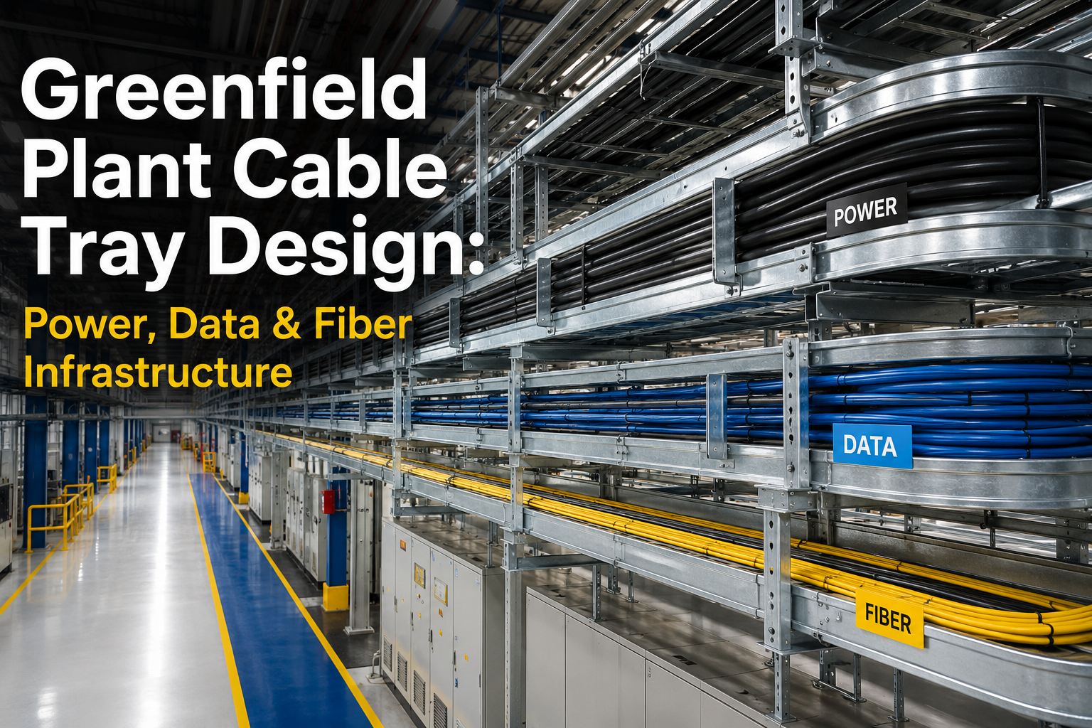
Separate trays for network/data cables — never shared with power cables. Size for 40-50% fill on day one to allow future expansion. Typical factory: 300mm wide × 100mm deep for 20-40 CAT6A runs per tray section. Ladder-type trays for ventilation; solid-bottom trays where cable protection is needed. Mount at minimum 300mm separation from power trays (TIA-568 / IEC 61918).
Fiber Tray / Innerduct
Fiber routed in separate innerduct or micro-duct within the cable tray system. Minimum bend radius maintained at all turns (OM4: 7.5mm for bend-insensitive; OS2: 10mm). Fiber splice/distribution points at each IDF (intermediate distribution frame) location. Pull boxes at direction changes exceeding 90° and every 30m of straight run.
Tray Routing on Floor Plans
Cable tray routes marked on architectural reflected ceiling plans (RCP) and floor plans during design phase. Coordinate with HVAC ductwork, fire suppression piping, and lighting — cable trays compete for ceiling space. Greenfield advantage: trays routed first, then other trades coordinate around them. In retrofit, cable trays get whatever space is left.
Drop Points & Consolidation Points
Cable drops from overhead trays to machine-level junction boxes or consolidation points at each equipment cluster. Industrial-grade junction boxes (IP54-IP67) specified per zone environmental rating. Consolidation points reduce the number of individual cable runs to the main tray — simplifying future moves, adds, and changes.
Environmental Cable Ratings
| Factory Environment | Hazards | Cable Jacket Required | Connector Type | IP Rating |
|---|---|---|---|---|
| Clean Assembly | Minimal — dust, static | Standard PVC or LSZH | RJ45 or M12-X | IP20-IP30 |
| General Manufacturing | Oil mist, moderate dust, vibration | Oil-resistant PUR or TPE jacket | M12-X (preferred) or shielded RJ45 | IP54-IP65 |
| Heavy Machining / Welding | Metal chips, cutting oil, EMI from welders, sparks | Oil/coolant-resistant PUR + braided shield | M12-X with metal housing | IP67 |
| Wash-Down / Food | High-pressure water, chemicals, sanitizers | FDA-compliant PUR or silicone; smooth outer jacket | M12-X stainless steel | IP67-IP69K |
| High Temperature (>60°C) | Radiant heat, hot surfaces, furnace proximity | Teflon (FEP/PFA) or silicone jacket; 200°C rated | High-temp M12 or specialized connectors | IP65+ |
| Outdoor / Between Buildings | UV, rain, temperature cycling, rodents | UV-stabilized PE; armored for direct burial | Weatherproof industrial connectors | IP67-IP68 |
Not sure which cable ratings your factory zones need? Plan Your Cable Infrastructure — we specify cable type, jacket material, connector, and IP rating per zone based on your actual factory environment.
Switch & Patch Panel Placement
Ethernet has a 100m total channel limit (90m permanent link + 10m patch). Every connected device must be within 90m horizontal cable distance of a managed switch. In greenfield, switch locations are plotted on the factory layout during design — ensuring every machine cell, inspection station, and sensor cluster is within range.
Wall-mounted or floor-standing network cabinet in each production zone. Houses access switches, fiber patch panels, and PoE power supplies. Climate-controlled (fan or AC) if ambient temperature exceeds 40°C. Minimum 4U rack space per 24-port switch, plus 2U for fiber patch panel, plus 2U for cable management. Size for 30-50% expansion.
Central fiber patch panel connecting all IDF locations via the backbone ring. Houses core switches, routers, and firewall equipment. Fiber patch panels for backbone termination — typically 12-48 fiber LC/SC connectors per panel. Cable management: 1U horizontal cable manager per 2U of equipment.
Every cable run documented: from-device, to-device, cable type, length, tray route, connector type at each end. Greenfield deliverable: a complete cable schedule spreadsheet that contractors bid directly from — eliminating estimation errors, material waste, and change orders. Typical factory: 500-5,000 individual cable runs documented.
Fiber Termination & Testing
Connector Types
LC (Lucent Connector) is the standard for new installations — small form factor, high density. SC for legacy compatibility. MPO/MTP for high-density trunk cables (12-24 fibers per connector) between MDF and IDF. Specify connector type in the cable schedule to ensure correct patch panels and transceivers are ordered.
Fusion Splicing vs. Mechanical
Fusion splicing: lower insertion loss (0.02 dB vs 0.5 dB), more reliable long-term. Required for singlemode (OS2) and recommended for all backbone fiber. Mechanical splicing acceptable for temporary or emergency repairs only. Greenfield: specify fusion splicing for all permanent fiber connections in the cable schedule.
Testing & Certification
Every fiber link tested with OTDR (Optical Time-Domain Reflectometer) for loss, length, and reflectance events. Every copper link tested with Fluke or equivalent channel tester to TIA-568 Category 6A standards. Test results documented per link and archived as part of as-built package. Failed links repaired and retested before acceptance.
Labeling & Documentation
Every cable, patch panel port, and switch port labeled with machine-readable and human-readable identifiers. Labeling scheme: Building-Floor-Zone-Rack-Port (e.g., B1-1-MFG-IDF3-P12). As-built cable schedule updated after installation to reflect actual routing and lengths. Stored in CMMS or network management system for lifecycle management.
Key Benefits & ROI
Every Cable Run Planned on Paper Saves $100 in Rework on Site
iFactory designs complete industrial cabling infrastructure for greenfield factories — cable type selection, tray sizing, switch placement, environmental ratings, and complete cable schedules — delivered as construction-ready documentation that contractors build from directly.
Frequently Asked Questions
Wrong Cable = Re-Pull. Wrong Tray = Re-Build. Wrong Spec = Re-Do Everything.
Get it right on paper before the first conduit is installed. Complete cable schedules, tray sizing, and environmental specifications designed for your specific factory.