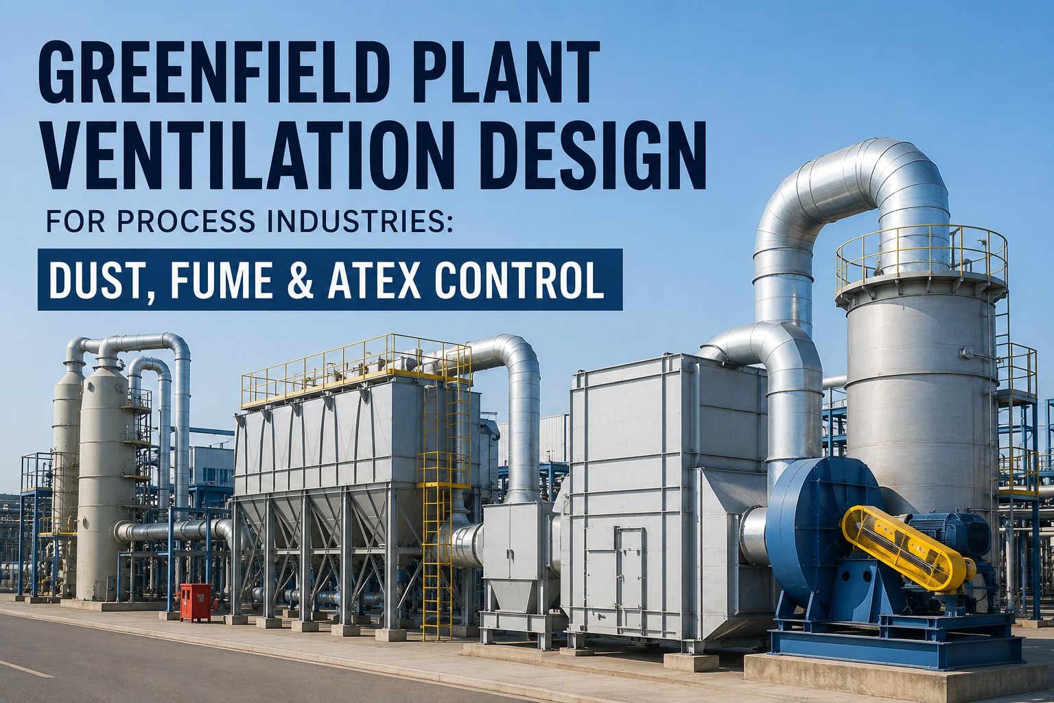
Ventilation design failure in a process industry plant is not an HVAC problem — it is a safety and compliance problem. An undersized dust collection system in a food processing plant allows combustible dust concentrations to build toward the Minimum Explosive Concentration. A fume extraction system with incorrect duct velocity allows particulates to settle and accumulate inside the ductwork — creating the fuel load for a duct fire. An ATEX zone classification based on incorrect ventilation assumptions installs Category 3 equipment in what is actually a Zone 21 environment — creating an ignition source at the heart of an explosive atmosphere. In a greenfield plant, every one of these hazards is designed out or designed in during the ventilation engineering phase. Book a greenfield ventilation design consultation to validate your process exhaust specifications, ATEX zone classification, and airflow model before ductwork drawings are issued.
Greenfield Plant Ventilation Design — Process Industries 2026
Four Ventilation System Types — Each Solving a Different Process Hazard
Process Exhaust
Captures and removes hazardous fumes, vapours, and heat at source before they enter the working environment
Welding, chemical processing, coating, soldering, thermal processes
OSHA 1910.94 / ACGIH IVE
Dust Collection
Captures, transports, and filters combustible or nuisance dust generated by grinding, milling, bagging, and conveying operations
Food, pharma, wood, metal powder, grain, cement processing
NFPA 652/654 / ATEX Directive / EN 60079-10-2
Fume Scrubbing
Wet or dry chemical treatment of exhaust gas streams containing acid gases, alkaline vapours, or toxic chemical fumes before discharge to atmosphere
Chemical, semiconductor, battery manufacturing, surface treatment
EPA 40 CFR / Local EA Permits / ISO 14001
General Dilution
Whole-space ventilation to maintain indoor air quality, control temperature, and dilute low-level contaminants across general production areas
Assembly, warehousing, packaging, light manufacturing
ASHRAE 62.1 / CIBSE Guide A / EN 16798-3
60%
Energy savings achievable with demand-based ventilation control vs. fixed-speed fans
Zone 22
Most common ATEX dust classification — found in most facilities handling any combustible powder
1 mm
Combustible dust layer thickness on a hot surface can ignite without a dust cloud present
4 to 8x
Cost multiplier to retrofit ventilation into a completed process facility vs. at greenfield design
ATEX Zone Classification: The Ventilation Decision That Drives Every Equipment Specification
ATEX (ATmosphères EXplosibles) zone classification determines which equipment categories can be installed in which areas of your plant — and ventilation is the primary design tool that either creates, reduces, or eliminates those zones. Get the zone classification wrong and you either install explosive atmosphere-rated equipment at unnecessary cost in non-hazardous areas, or — critically — install inadequately rated equipment in a genuine explosive atmosphere zone. In a greenfield plant, ATEX zone classification is performed before equipment layout is finalized — because the zone extent around each release source determines the required equipment category within that radius.
ATEX Zone Classification — Gas/Vapour Zones and Dust Zones
Gas / Vapour Zones (Flammable liquids and gases)
Zone 0
Explosive atmosphere present continuously or more than 1,000 hours per year
Inside vessels, tanks, reactors, silos with flammable liquid or gas
Equipment category: Cat 1G (Ex ia, Ex ma) — safest, highest protection
Ventilation: Cannot eliminate Zone 0 inside process equipment — isolate instead
Zone 1
Explosive atmosphere likely to occur occasionally in normal operation (10 to 1,000 hrs/yr)
Immediately around Zone 0 sources: pump gland areas, open filling points, pit sumps
Equipment category: Cat 1G or 2G (Ex d, Ex e, Ex p, Ex ia)
Ventilation: Adequate dilution can reduce Zone 1 extent — must be documented in EPD
Zone 2
Explosive atmosphere unlikely in normal operation, and if present persists only briefly (less than 10 hrs/yr)
Areas around flanged joints, vents, secondary containment, solvent storage rooms with dilution
Equipment category: Cat 1G, 2G, or 3G
Ventilation: High-dilution ventilation can reduce Zone 2 extent significantly — key design tool for cost reduction
Dust Zones (Combustible powders and dusts)
Zone 20
Explosive dust cloud present continuously or for long periods
Inside mills, pneumatic conveyors, silos, dust collectors during operation
Equipment category: Cat 1D (IP6X rated, Ex t or Ex ia) — highest dust protection
Ventilation: Cannot eliminate Zone 20 inside equipment — use explosion protection (NFPA 69)
Zone 21
Explosive dust cloud likely to occur occasionally in normal operation
Bagging points, open inspection ports, filling/emptying stations, filter change areas
Equipment category: Cat 1D or 2D (IP6X)
Ventilation: LEV at source during operation can reduce Zone 21 extent — critical for cost of equipment specification
Zone 22
Explosive dust cloud unlikely but possible — the most common dust zone classification
General areas of facilities handling combustible powder — flour mills, sugar processing, pharmaceutical manufacturing
Equipment category: Cat 1D, 2D, or 3D (IP5X minimum)
Ventilation: Good general dilution and dust suppression reduces Zone 22 extent — key cost reduction tool in food, pharma, chemical plants
Critical: A ventilation failure that reverts a Zone 2 to Zone 1 (or Zone 22 to Zone 21) while inadequately rated equipment is installed creates an immediate non-compliance and an immediate explosion risk. The ventilation system that enables any zone reduction must be on the critical equipment register with defined failure alarms — specified at greenfield design, not discovered at first inspection.
Not sure which ATEX zones apply to your process areas? Book a greenfield ventilation and ATEX consultation — we will review your process hazard profile and produce a zone classification drawing before your equipment layout is finalized.
Dust Collection System Design: The Decisions That Determine Compliance and Safety
Dust collection system failure in a process plant is rarely caused by a broken fan — it originates in poor system design, incorrect dust characterization, or inadequate capacity planning at the engineering phase. The dust explosion pentagon — dust cloud, oxygen, ignition source, confinement, and dispersion — means that a dust collection system that works below design capacity is not just a compliance problem. It is the fuel supply system for a potential explosion. Every design decision below is a greenfield engineering call.
01
Dust Characterization — Before Any System Is Sized
Dust collection system design starts with dust testing — not fan selection. The critical dust parameters that drive system specification are: Minimum Explosive Concentration (MEC in g/m³), Kst value (explosion severity index), Minimum Ignition Temperature (MIT) for both cloud and layer, and Minimum Ignition Energy (MIE in mJ). These values are specific to your actual material — published tables are starting points only, as particle size distribution, moisture content, and surface treatment all affect explosion characteristics. A system designed for the wrong Kst value installs the wrong explosion vent area. Wrong MEC assumptions size the wrong dust concentration monitoring alarm threshold.
Design rule: Commission dust explosion testing on representative samples of your actual process material before dust collection system design begins. Do not use published generic values for ATEX zone classification or explosion protection sizing without testing confirmation.
02
Duct Transport Velocity — The Safety-Critical Number Most Engineers Get Wrong
Transport velocity is the minimum duct air velocity required to keep particulates in suspension and moving toward the collector — it must not drop below this value anywhere in the system. Too low and dust settles in the ductwork, creating a fuel load for a duct fire. Too high and the ductwork abrades rapidly, creating sparks and increasing maintenance cost. The correct transport velocity is material-specific: light wood dust requires 17 to 20 m/s; heavy metal chips require 25 to 30 m/s; grain dust 18 to 22 m/s; pharmaceutical powder 15 to 20 m/s. These values must be maintained at the design flow rate — and the system must be re-commissioned if any branch is added, removed, or modified that changes the overall duct resistance.
Design rule: Calculate transport velocity at every duct section — not just the main header. Horizontal duct runs are the highest settling risk. Size the fan for the maximum resistance condition, not the average. Commission a pitot traverse test at every main duct section before plant handover.
03
Explosion Protection — Venting, Suppression, and Isolation in the System Design
Every dust collector handling combustible dust must have explosion protection designed into it — not added to it as an afterthought. The two primary approaches are explosion venting (NFPA 68 / EN 14491) and explosion suppression (NFPA 69). Explosion vent area is calculated from Kst, reduced pressure, and equipment volume — typically located on the collector housing top or sides with a discharge path to safe area. Isolation prevents flame and pressure propagating back through the ductwork to the process equipment (NFPA 69 / EN 15089). In a greenfield plant, explosion vent discharge direction, discharge area clearance, and isolation valve positions are structural elements of the building layout — they must be confirmed before ductwork routing is fixed.
Design rule: Calculate explosion vent area before equipment is procured — vent area is a core specification, not an option. Confirm vent discharge direction on building drawings. Specify isolation valves (chemical or mechanical) at every connection between the collector and process equipment or ductwork branches.
Duct Velocity Reference Guide by Material Type
Getting transport velocity wrong at greenfield design is expensive in both directions. Under-velocity causes material deposition and duct fires. Over-velocity causes abrasion of duct walls, excessive noise, and energy waste. These values are design starting points — actual system velocity should be verified by a ventilation engineer against your specific material's particle size distribution, bulk density, and Kst value.
Material / Dust Type
Min Transport Velocity
Recommended Range
Filter Type
ATEX Zone Risk
Light wood dust / sawdust
17 m/s
17 to 20 m/s
Cartridge or bag filter — ATEX-rated collector
Zone 21 / 22 — Kst up to 200 bar·m/s
Grain / cereal dust
18 m/s
18 to 22 m/s
Bag filter with pulse-jet cleaning
Zone 21 / 22 — highly combustible
Pharmaceutical powder
15 m/s
15 to 20 m/s
HEPA bag filter — contained clean-in-place
Zone 20 / 21 inside equipment — material-specific testing required
Welding fume / metal smoke
10 m/s
10 to 15 m/s
Cartridge filter, H14 HEPA for stainless welding fume
NFPA 484 — metal dust combustibility depends on metal type
Sugar / confectionery dust
20 m/s
20 to 25 m/s
Bag filter with explosion vent (Kst ~165 bar·m/s)
Zone 21 — MEC low (approx 30 g/m³)
Cement / fly ash
20 m/s
20 to 25 m/s
Bag filter — non-combustible, ATEX not required
Non-combustible — standard equipment
Heavy metal chips / turnings
25 m/s
25 to 30 m/s
Cyclone separator primary + bag secondary
NFPA 484 — assess per metal; aluminum Kst up to 300 bar·m/s
Chemical / process fume
Contaminant-specific
Designed to OEL capture velocity at hood face
Wet scrubber or carbon bed depending on gas type
Depends on gas LEL — flammable gases require ATEX assessment
Validate Your Ventilation Design Before Ductwork Drawings Are Issued
iFactory's greenfield ventilation consultation covers dust characterization requirements, ATEX zone classification per process area, dust collection system sizing, duct transport velocity calculations, explosion protection specification, fume scrubber selection, and AI-assisted airflow modeling — all before your ventilation contractor prices the ductwork installation.
Fume Extraction vs. Wet Scrubbing vs. Carbon Adsorption: Choosing the Right Treatment Train
Process exhaust treatment is not a single technology decision — it is a treatment train decision based on the chemical composition of the exhaust stream, the emission limit value (ELV) the process must meet at the point of discharge to atmosphere, and the recoverable value (if any) of the captured material. In a greenfield plant, the treatment train is designed before the exhaust ducting is routed — because the equipment dimensions, footprint, and support structure are architectural elements that must be planned into the building layout before construction begins.
Local Exhaust Ventilation (LEV)
Captures contaminants at source using hoods, enclosures, or receptor openings before they disperse into the room air. Transport ductwork delivers to collector or scrubber.
Hood face velocity0.25 to 0.75 m/s at hood face depending on toxicity (ACGIH IVE design criteria)
Capture envelopeMust cover 100% of emission source — verify with smoke visualisation testing at commissioning
COSHH complianceLEV must reduce worker exposure below WEL/OEL — measured by personal air monitoring after commissioning
First line for all process areas — cannot be omitted. All other treatment technologies are end-of-pipe and cannot substitute for LEV at source.
Wet Scrubber
Passes contaminated exhaust gas through a liquid (typically water or caustic/acid solution) to absorb soluble gases, neutralize acid/alkaline fumes, and cool hot gas streams before discharge
Best forAcid gases (HCl, HF, SO₂, HNO₃), alkaline fumes (NH₃), soluble VOCs, hot and moist process streams
Removal efficiency95 to 99%+ for soluble gases at correct pH and contact time — verified by stack testing against environmental permit limit
Greenfield requirementEffluent treatment for scrubber blowdown must be designed into the building services — liquid waste cannot discharge direct to drain
Required for chemical, semiconductor, and surface treatment exhaust streams. Scrubber location (typically on mezzanine or roof) must be in building layout before structural steel is designed.
Activated Carbon Adsorption
Passes exhaust air through beds of activated carbon which adsorb organic vapours, odours, and low-concentration VOCs. Beds are either regenerated in-place or replaced when saturated.
Best forVOC control at low concentration, odour abatement, solvent recovery (high concentration + regeneration), paint booth exhaust
Not suitable forHigh humidity streams (water competes with VOC for active sites), ketones (exothermic adsorption), very high VOC concentrations (fire risk in bed)
Greenfield requirementCarbon bed weight and footprint must be in structural drawing — large beds on roof or mezzanine require structural provision
Standard for solvent-based coating and printing operations, pharmaceutical solvent handling, and any process requiring odour or VOC abatement to planning consent limits.
Expert Perspective: Ventilation Failure in a Process Plant Is Not a Nuisance — It Is a Safety Event
The most dangerous failure mode in process plant ventilation is not a catastrophic fan failure — it is a gradual performance degradation that no one notices until the ATEX zone it was suppressing reverts to a higher hazard category while inadequately rated equipment is running inside it. This happens when a filter loads and duct resistance rises, reducing transport velocity below design. It happens when a branch is added to the system without re-commissioning. It happens when a fan impeller erodes and nobody checks the actual flow rate. In each case, the ventilation system that justified a Zone 22 classification is now providing insufficient dilution for Zone 22 — and the equipment installed based on that classification is suddenly non-compliant with the real zone. Digital twin airflow modeling at greenfield design, combined with continuous air quality monitoring and fan power monitoring in the operational plant, is the only architecture that prevents this from happening without someone noticing. Designing this monitoring in from day one costs a fraction of the regulatory and safety consequence of discovering it under enforcement.
— iFactory Greenfield Consulting, Process Safety Engineering Practice 2025 to 2026
60%
Energy savings from demand-controlled ventilation with VFD fans vs. fixed-speed operation
Zone 22
The most common ATEX dust zone — found in virtually every facility handling combustible powder
4 to 8x
Cost multiplier for retrofitting process ventilation into a completed plant vs. greenfield specification
Ready to model your greenfield plant's ventilation and ATEX zone interaction in a digital twin before structural drawings are issued? Talk to our process ventilation team — we will review your hazard profile and produce an ATEX zone map and ventilation specification before equipment layout is finalized.
Design Your Greenfield Plant Ventilation for Process Safety and ATEX Compliance
iFactory's greenfield ventilation consultation covers dust characterization, ATEX zone classification mapping, dust collection system sizing and explosion protection specification, duct transport velocity calculations, fume treatment train selection, LEV hood design brief, continuous air quality monitoring specification, and digital twin airflow model validation — before ductwork drawings are issued.
Frequently Asked Questions
What is the difference between ATEX Zone 21 and Zone 22 for dust, and how does ventilation change the classification?
Zone 21 is where an explosive dust cloud is likely to occur occasionally during normal operation — typically at bagging points, open filling stations, and frequently-opened inspection ports. Zone 22 is where an explosive dust cloud is unlikely during normal operation but possible — and includes areas where combustible dust layers accumulate and could be disturbed. Zone 22 is the most common dust zone classification and is present in virtually any facility handling combustible powder including flour, sugar, pharmaceutical material, and metal powder. Adequate local exhaust ventilation at Zone 21 sources can reduce the extent of the Zone 21 area — but cannot eliminate the zone at the source itself. Zone reductions enabled by ventilation must be documented in the Explosion Protection Document (EPD) and the ventilation system must be on the critical equipment register with failure alarms.
What is transport velocity in dust collection and why is it the most critical design number?
Transport velocity is the minimum air velocity in the ductwork required to keep dust particles in suspension rather than allowing them to settle and accumulate. Below transport velocity, dust deposits on the duct floor and progressively reduces the effective duct area — increasing resistance and further reducing velocity in a self-reinforcing failure. Accumulated dust in a duct run is the fuel load for a duct fire. The correct transport velocity is material-specific: light wood dust requires 17 to 20 m/s, heavy metal chips 25 to 30 m/s. It must be maintained at every section of the system — not just the main header — and verified by pitot traverse testing at commissioning. Any modification to the system (adding or removing branches) requires recommissioning of the transport velocity throughout.
When is a wet scrubber required for process exhaust treatment and when is activated carbon used instead?
Wet scrubbers are required for soluble gas streams — acid gases (HCl, HF, SO₂, HNO₃), alkaline fumes (NH₃), and hot moist process exhaust that cannot pass through a carbon bed without moisture pre-treatment. Scrubbers achieve 95 to 99%+ removal efficiency for soluble gases at correct liquid contact time and pH. Activated carbon adsorption is used for low-concentration organic vapours, solvent emissions, paint booth VOCs, and odour control — it cannot handle high humidity streams or highly concentrated VOC streams where the exothermic heat of adsorption creates a fire risk in the bed. Many process exhaust treatment trains combine both: a wet scrubber for acid gases and particulate removal, followed by a carbon bed for residual VOC polishing to meet planning consent emission limits.
Why must explosion vent direction and area be specified before ductwork is routed in a greenfield plant?
Explosion vent area for a dust collector is calculated from the Kst value of the dust, the reduced maximum pressure, and the equipment volume — it is a structural specification of the collector, not an optional feature. The vent must discharge to a safe area — typically outdoors, away from personnel access routes and building openings. The discharge direction and clearance distance from the vent to any personnel area or building aperture must be confirmed before the collector position and surrounding building structure are designed. If the discharge direction is determined after structural steel erection, the result is either expensive structural modification or a vent that discharges into an occupied area — which fails the explosion protection purpose entirely. In a greenfield plant, vent direction and clearance zone are on the building layout drawing and must be confirmed before structural steel is ordered.
How does iFactory's greenfield ventilation and ATEX consultation work?
iFactory's greenfield ventilation consultation covers your process hazard profile and contaminant characterization, ATEX zone classification mapping for gas, vapour, and dust zones with documented EPD basis, dust collection system design brief (sizing, filter type, explosion protection specification), duct transport velocity calculations per material type, explosion vent direction confirmation on building layout drawing, fume extraction hood design brief, scrubber or carbon bed selection and footprint provision, continuous air quality monitoring specification, VFD fan control strategy for energy optimization, and digital twin airflow model validation. All outputs are specification documents your ventilation engineer and structural contractor work from directly.
Book your greenfield ventilation consultation here.