Top 10 Greenfield Plant Lighting Design Strategies for AI Vision Systems
By Riley Quinn on June 19, 2026
Lighting is the single most underspecified variable in greenfield AI vision system design — and the most expensive to get wrong. AI models trained on well-lit, consistent images achieve 99%+ defect detection accuracy. The same models operating under uncontrolled ambient lighting, ambient glare, and moving shadows swing 15 to 30% in accuracy between morning and afternoon on the same production line. Retrofit lighting solutions applied to a completed facility cost 4 to 8 times more than specifying the correct lighting architecture during greenfield design — because they require custom brackets on finished structures, cables routed through completed ceilings, and enclosures cut into finished walls. Book a greenfield AI vision lighting consultation to have your inspection zone lighting geometry validated before structural steel is placed.
Greenfield Plant Lighting Design — AI Vision Systems 2026
Why Lighting Is the First AI Vision Decision — and What Happens When You Get It Wrong
Uncontrolled Ambient Lighting
80 to 85%
Detection accuracy
15 to 30% accuracy swing between shifts
Moving shadows mask surface defects
Glare on reflective surfaces masks defects
AI model requires constant retraining
Retrofit cost: 4 to 8x design-phase cost
Engineered AI Vision Lighting
99 to 99.4%
Detection accuracy
Consistent image quality across all shifts
Zero ambient light interference
95% fewer false positives from glare
AI model stable — minimal retraining
Specified at greenfield design — no retrofit cost
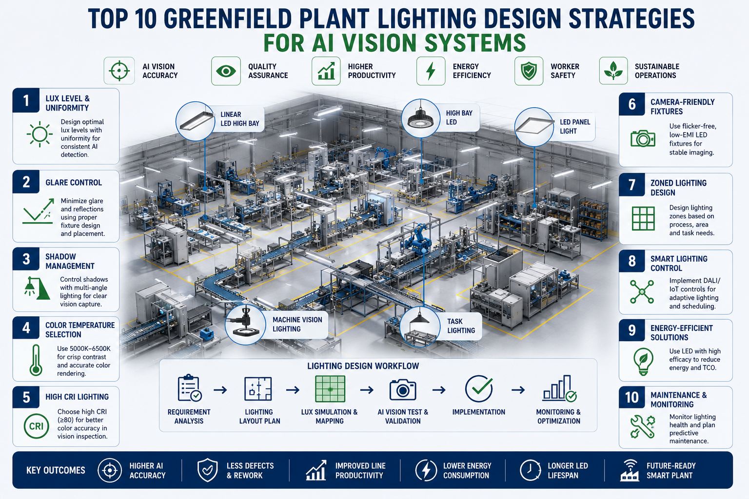
The 10 Lighting Design Strategies — In Priority Order
The strategies below are ordered by design-phase impact — the ones that are hardest to fix after construction come first. Every strategy is a greenfield decision point that costs a fraction of retrofit if addressed during the engineering phase.
01
Design Inspection Enclosures Into the Factory Layout
Ambient light — from skylights, windows, overhead bay fixtures, and shift-to-shift sun angle changes — creates lighting variability that AI models cannot compensate for. The only reliable fix is a light-isolated inspection enclosure or blackout zone that controls every photon reaching the camera sensor. In a greenfield facility, this enclosure is designed into the factory layout and structural drawings before steel is placed. In a retrofit, it means cutting into finished walls, relocating utilities, and custom-fabricating enclosures around existing conveyors — at 4 to 8 times the greenfield cost.
Design rule: Specify inspection enclosure dimensions on architectural floor plan drawings. Minimum enclosure depth: camera working distance + 150mm for light fixture mounting. Include utility penetrations for power, network, compressed air (for positive pressure dust exclusion), and maintenance access.
02
Match Lighting Technique to Surface Type — Not Just Brightness
Retrofit difficulty: High — wrong technique requires fixture replacement and repositioning
Critical
Lighting technique determines what the camera sees — not how bright the image is. Wrong technique produces high-lux images that hide the defects you are trying to find. The four primary techniques have fundamentally different geometric properties that depend on the surface being inspected.
Brightfield
Light source perpendicular to surface (90°)
Best for matte, non-reflective surfaces — reveals texture and print contrast
Avoid on polished metal — creates glare hotspots that mask defects
Darkfield
Light source at low oblique angle (5° to 45° off horizontal)
Best for surface scratches, raised edges, cracks — defects scatter light into camera
Avoid on textured or embossed surfaces — background noise overwhelms signal
Coaxial (DOAL)
Light along optical axis via beam splitter
Best for highly reflective flat surfaces — specular reflection returns uniformly
Avoid on curved or 3D surfaces — off-axis geometry breaks uniform return
Diffuse Dome
Omni-directional scatter from dome enclosure
Best for complex 3D shapes — eliminates shadows and specular hotspots simultaneously
Avoid for edge detection — removes shadow cues needed to resolve edges
Design rule: Determine lighting technique per inspection station from surface material, geometry, and defect type — before specifying fixture type or lux level. Technique selection drives mounting geometry, which drives enclosure dimensions.
03
Build a Zone-by-Zone Lux Map Before Fixture Specification
Retrofit difficulty: Medium — under-lit zones require additional fixtures and cable runs
High Priority
Different zones in an industrial plant have fundamentally different lighting requirements — not just in lux level, but in uniformity ratio, color rendering index, and ambient interference risk. Specifying a single lighting design for the entire facility guarantees that AI vision inspection zones are either over-lit (generating glare) or under-lit (losing contrast). A zone-by-zone lux map, completed before fixture specification, drives the right fixture type, mounting height, and circuit layout for each area.
All illumination from camera-synchronized strobe — no ambient contribution. Blackout enclosure required.
Precision Assembly
1,000 to 2,000 lux
90+
High CRI critical — color differentiation errors at CRI <80 affect inspection decisions
Quality Control Lab
750 to 1,500 lux
90+
Color-accurate inspection requires consistent CCT — use single fixture type, single batch per zone
General Production Floor
300 to 500 lux
80+
Avoid mounting fixtures directly above camera FOV — ceiling glare reflects into lens
Warehouse / Storage
150 to 300 lux
70+
If AI barcode / label scanning present, increase to 500 lux at scanner height
Loading Dock / External
100 to 200 lux
65+
Gate camera systems need anti-backscatter hoods — headlights otherwise saturate sensors
Design rule: Commission a point-by-point photometric simulation (DIALux or Relux) before fixture procurement. Uniformity ratio target for inspection zones: maximum to minimum lux ratio not exceeding 1.5:1 across the camera field of view.
04
Select Color Temperature by Inspection Task — Not Aesthetics
High Priority
Color temperature (CCT) in Kelvin shifts how colors appear in camera images — and affects AI model accuracy on color-coded inspection tasks. A model trained at 5,000 K cool white produces different pixel values on the same object at 3,000 K warm white. For monochrome cameras: CCT matters less — choose by spectral match to camera sensor peak sensitivity (typically 550 to 700 nm). For color cameras used in color-based inspection: specify 5,000 K to 6,500 K cool white (closest to D65 standard illuminant) and keep all fixtures in an inspection zone from the same manufacturer batch to avoid inter-fixture CCT variance of more than 200 K.
Use 5,000 to 6,500 K for color cameras. Match spectral peak to sensor QE curve for monochrome. Never mix CCT within a single inspection zone.
05
Specify Strobe Synchronization From the Controls Architecture
High Priority
Fast-moving products on conveyors moving at 0.5 to 3 m/s require strobe lighting synchronized to camera trigger — continuous lighting at those speeds produces motion blur that destroys image sharpness. A 1 ms strobe duration at 2 m/s line speed produces 2 mm of motion blur in the image — enough to destroy resolution on defects smaller than 3 mm. In a greenfield facility, strobe synchronization is designed into the controls architecture: the encoder on the conveyor generates a trigger signal, which fires both the camera and the LED strobe controller simultaneously via a synchronized trigger line. This electrical infrastructure must be specified on control system drawings before construction, as cabling routes from encoder to camera to strobe controller are determined during design.
Specify trigger cable routes and encoder positions on conveyor drawings. Strobe pulse width: 50 to 200 µs typical. Maximum allowable motion blur: 10% of minimum detectable defect size.
06
Design Glare Exclusion Geometry Into the Fixture Position
High Priority
Glare — specular reflection of the light source into the camera lens — masks surface defects by saturating pixel regions with white. The "glare zone" on any surface is geometrically predictable from the light source position, surface material, and camera angle: it is the mirror reflection angle of the source from the surface normal. In a greenfield facility, glare exclusion is designed by positioning fixtures outside the calculated glare zone for each inspection geometry. This means calculating the illumination geometry (sometimes called the "W" diagram — source position, surface, camera position) and confirming the fixture falls outside the specular return cone. Retrofit lighting cannot escape a glare zone if the fixture mounting points are fixed — which is why greenfield specification is essential.
Plot source position, surface normal, and camera angle for every inspection station. Fixture must fall outside the specular cone (angle of incidence does not equal angle of reflection into lens). For reflective products, use diffuse dome or darkfield exclusively.
07
Specify LED Over All Legacy Sources for AI Vision Zones
Standard Practice
LED is the only light source appropriate for AI vision inspection in a new facility. Fluorescent tubes flicker at mains frequency (50 or 60 Hz) — producing alternating bright and dark image frames at rates that strobe synchronization cannot fully eliminate. Metal halide has a warm-up period of 2 to 5 minutes and color shift as it ages. High-pressure sodium has poor CRI (22 to 44) and monochromatic output that makes color inspection impossible. LED delivers instant-on operation, no flicker (when specified with constant-current driver, not PWM at low-frequency), output stability less than 0.5% variation across 50,000-hour life, and full strobe compatibility. For inspection zone fixtures: specify constant-current LED drivers — not PWM below 20 kHz, as low-frequency PWM reintroduces effective flicker.
Specify constant-current LED drivers for all AI vision zone fixtures. Minimum driver frequency for PWM: 20 kHz. Reject any fixture specification that does not include driver type documentation.
08
Plan Shadow Control for Structural Elements Above the Line
High Priority
Overhead beams, cable trays, conveyor frames, and HVAC ductwork cast shadows that move with sun position and personnel movement throughout the day. AI models trained on shadowless images produce false positives when shadows cross the inspection field — because the model has learned that a dark region at that location indicates a defect. In a greenfield facility, structural elements above camera fields of view are identified on the structural drawings and evaluated for shadow impact. Where shadow risk exists, three interventions are available: relocating the structural element, adding secondary fill lighting to neutralize the shadow, or enclosing the inspection station to exclude all ambient light. All three are trivial to implement at design phase and expensive after construction.
Mark all structural elements within 3 meters of camera FOVs on structural drawings. Simulate shadow angle at summer solstice sun position for your latitude. Specify fill lighting or enclosure where shadow risk is confirmed.
09
Separate Ambient and Inspection Lighting Circuits
Standard Practice
General plant lighting and AI vision inspection lighting must be on independent circuits with independent control. This enables three important operational capabilities: inspection zone lighting can be dimmed or extinguished independently during non-production periods for energy savings; camera strobes and synchronized lighting can be switched without affecting general area lighting; and emergency lighting tests or circuit maintenance cannot disrupt active inspection systems. In a greenfield facility, inspection lighting circuits are specified on the electrical drawings as dedicated circuits with their own panels and sub-distribution. Retrofit facilities often have inspection lighting daisy-chained to general circuits — which forces operational constraints that limit when and how inspection systems can be maintained.
Specify inspection lighting on dedicated 20 A circuits minimum, served from a UPS or clean power source. Label all inspection lighting circuits clearly on the electrical panel schedule and factory floor plan.
10
Include Lighting as a Variable in AI Model Training Protocol
Standard Practice
Even with excellent lighting design, real-world production introduces lighting variation: fixture aging reduces lux output by 3 to 5% per year; fixture replacements use slightly different bins with 2 to 5% lux variance; lens contamination from process dust or oil mist changes effective illumination at the sensor. AI models trained without accounting for these variations become brittle — requiring retraining every time lighting drifts beyond the model's training distribution. In a greenfield facility, the AI model training protocol is specified alongside the lighting design: training data is captured across multiple fixture lux levels, simulated end-of-life output, and contaminated lens conditions. This is only achievable before commissioning — once the line is live, capturing controlled contamination-state images during production is operationally disruptive.
Capture training images at 100%, 90%, and 80% lux output to simulate fixture aging. Include lens-contaminated images in training set. Schedule lux re-measurement every 6 months and set retraining trigger at 10% lux deviation from commissioning baseline.
Ready to validate your inspection zone lighting geometry before drawings are issued? Book a greenfield AI vision lighting consultation — our engineers will review your inspection station specifications and produce a lighting geometry analysis for each camera position.
Get Every Inspection Zone Lighting Geometry Validated at Design Phase
iFactory's greenfield AI vision consultation covers inspection enclosure dimensioning, lighting technique selection per surface type, lux mapping and photometric simulation, strobe synchronization specification, glare exclusion geometry, and construction-ready lighting blueprints — all delivered before a single fixture is purchased.
The 5 Most Common AI Vision Lighting Failures in Greenfield Plants
These are the failures iFactory engineers encounter most frequently in greenfield plants where lighting was treated as a post-design detail. Every one of them was preventable with the correct specification at the engineering phase.
F1
Window Glare at Morning and Evening Production Shifts
Root cause: Inspection stations placed near east or west-facing windows without glare analysis. Sun angle at 0600 and 1700 drives direct or reflected light into camera fields of view.
AI accuracy drops 20 to 35% during affected hours. Either production stops or defect escapes accumulate.
Greenfield fix: Orient inspection lines north-south on floor plan, or specify inspection enclosures with blackout treatment on south-facing surfaces.
F2
Ceiling Bay Lights Reflecting in Product Surface
Root cause: Standard high-bay LED fixtures mounted above inspection conveyors create specular reflections on polished, metallic, or wet product surfaces at angles that change with conveyor elevation variation.
Glare hotspots appear in camera images at the same locations where surface defects would appear — false positive rate rises above 15%, triggering constant operator override.
Greenfield fix: Specify glare-exclusion geometry analysis before fixture mounting height is confirmed. Use darkfield or diffuse dome technique for any reflective surface type.
F3
Structural Shadow Crossing Camera Field of View
Root cause: Overhead cable trays, conveyor supports, or HVAC ducts cast moving shadows into inspection fields as ambient light angle changes through the day.
AI model trained without shadows fires false positive on any shadow passing through the field — or if trained with shadows, misses real defects covered by shadow.
Greenfield fix: Mark all structural elements above camera FOVs on structural drawings and specify enclosure or shadow-neutralizing fill lighting before steel erection.
F4
PWM LED Flicker Producing Dark Frames
Root cause: Low-cost LED fixtures with PWM drivers at 1 to 10 kHz produce effective flicker that camera sensors at high frame rates (100+ fps) capture as alternating bright and dark frames.
Every 3rd to 5th frame is underexposed — AI classification becomes unreliable on affected frames, requiring either frame rejection logic or complete fixture replacement.
Greenfield fix: Specify constant-current LED drivers explicitly in fixture specification. Require driver documentation with purchase order. Verify with flicker meter before acceptance.
F5
Mixed CCT Fixtures Within a Single Inspection Zone
Root cause: Replacement fixtures from different batches or manufacturers installed in the same zone produce CCT variance of 300 to 600 K — altering color appearance within the same camera field of view.
Color-based inspection decisions (label color, product color verification) become unreliable at zone boundaries between old and new fixtures. AI model shows spatial accuracy degradation.
Greenfield fix: Specify fixture model, manufacturer, and batch number on the as-built drawing. Maintain a stock of commissioning-batch fixtures for replacement. Set up a lux and CCT monitoring program from day one.
Expert Perspective: Lighting Is an AI Vision Engineering Decision, Not a Facilities Decision
The most expensive AI vision mistake in greenfield design is treating lighting as a facilities and electrical decision rather than an AI engineering decision. Facilities teams select lighting for human comfort — adequate lux for safe working, acceptable glare reduction for ergonomics. AI cameras have completely different requirements: controlled illumination geometry to reveal specific defect types, strobe synchronization to freeze motion, spectral characteristics matched to camera sensor sensitivity, and full ambient exclusion to prevent model drift. When these requirements are not captured in the engineering specification before design freeze, the result is an AI vision system that achieves 80 to 85% detection accuracy instead of 99%+ — not because the AI is wrong, but because the lighting is wrong. Fixing lighting after construction typically costs $50,000 to $200,000 per inspection station in a live facility. Getting it right at greenfield design costs $2,000 to $8,000 per station in engineering time.
— iFactory Greenfield Consulting, AI Vision Engineering Practice 2025 to 2026
15 to 30%
AI accuracy swing between morning and afternoon on poorly lit inspection lines
4 to 8x
Retrofit cost multiplier vs. specifying correct lighting at greenfield design phase
95%
Fewer false positives from properly engineered lighting geometry vs. uncontrolled ambient
Planning AI vision inspection for a new facility? Talk to our greenfield vision engineering team — we produce construction-ready lighting blueprints as part of the AI camera placement and inspection station design package.
Build AI Vision Lighting Right From the Start — Not After Construction
iFactory's greenfield AI vision consultation covers all 10 lighting design strategies — inspection enclosure design, lighting technique selection per surface, photometric lux simulation, strobe synchronization specification, glare exclusion geometry, CCT selection, and fixture documentation — delivered as construction-ready blueprints your architects and contractors build from directly.
What lux level does an AI vision inspection station actually need?
AI vision inspection stations do not have a single lux requirement — they have a lighting consistency requirement. The inspection zone must be illuminated only by its dedicated synchronized strobe, with all ambient light excluded by the enclosure. The strobe lux level is determined by the camera sensor sensitivity, the lens aperture, the strobe pulse duration, and the reflectance of the surface being inspected — typically set to achieve a target image gray level of 180 to 220 (out of 255) on a reference target. What matters is not peak lux but uniformity ratio: the maximum to minimum lux variation across the camera field of view should not exceed 1.5:1.
When should darkfield lighting be chosen over brightfield for industrial AI vision?
Darkfield lighting — illuminating at a low oblique angle of 5 to 45 degrees off horizontal — is the correct choice when the inspection task requires detecting surface features that scatter or reflect light differently from the surrounding background. This includes scratches, cracks, raised edges, surface contamination on matte materials, and embossed text on flat backgrounds. The oblique angle causes surface irregularities to scatter light toward the camera while the flat background reflects the light away. Brightfield (perpendicular illumination) is better for detecting print contrast, color differences, and dimensional features on non-reflective surfaces. Wrong technique choice is the most common cause of poor AI detection performance even with good lux levels.
Why does PWM LED flicker cause AI vision problems and how do you prevent it?
PWM (Pulse Width Modulation) LED drivers reduce brightness by rapidly switching the LED on and off at frequencies between 100 Hz and 20 kHz. At high camera frame rates (100 to 500 fps), the camera shutter can capture frames during the LED off-time — producing dark or underexposed images in the inspection sequence. AI models trained on properly exposed images produce errors on dark frames. The prevention is simple: specify constant-current LED drivers in the fixture specification, which provide continuous smooth current regulation rather than switching. This should be a mandatory procurement requirement for all AI vision zone fixtures — and should be verified with a flicker meter at commissioning acceptance, not taken on trust from the fixture data sheet.
How are strobe lighting and camera triggering synchronized in a greenfield plant?
Synchronization is achieved through a hardware trigger chain: a rotary encoder mounted on the conveyor shaft generates a position pulse for every set distance of product travel (typically 0.5 to 2 mm per pulse). This encoder signal is fed to the vision controller, which fires both the camera shutter and the LED strobe driver simultaneously via dedicated trigger cables — producing a synchronized exposure where the strobe illuminates the product during exactly the camera integration window. The strobe duration (typically 50 to 200 microseconds) freezes motion blur while providing sufficient exposure. This trigger infrastructure — encoder selection, cable routes, vision controller I/O, and strobe driver location — must be specified on control system and electrical drawings during greenfield design.
How does iFactory design AI vision lighting as part of a greenfield consultation?
iFactory's greenfield AI vision consultation covers the complete lighting specification workflow: inspection enclosure dimensioning per camera working distance and product size, lighting technique selection per surface material and defect type, lux map simulation using photometric software, glare exclusion geometry calculation for each inspection station, strobe synchronization specification including encoder selection and cable routes, CCT and CRI specification per zone, fixture documentation requirements, and post-commissioning maintenance protocol including lux measurement cadence and retraining triggers. All outputs are delivered as construction-ready specification documents — not recommendations but drawings your architects and contractors build from directly. Book your greenfield AI vision lighting consultation here.