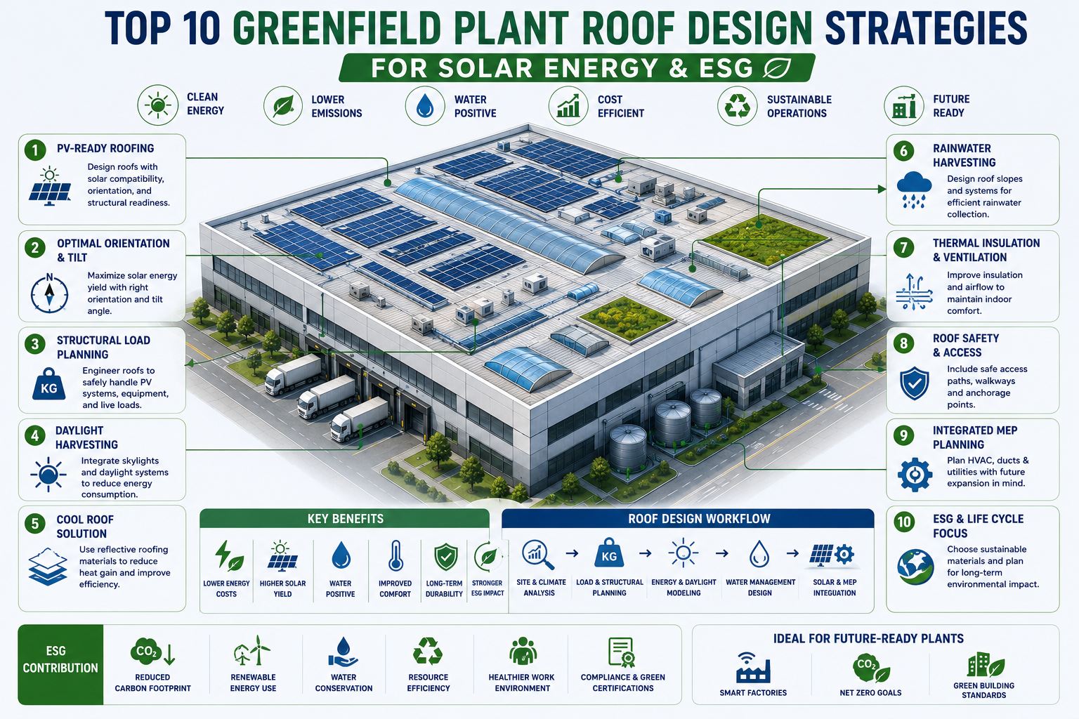
An industrial plant roof is the largest single horizontal surface on the site — typically 5,000 to 50,000 square metres of asset that most greenfield projects treat as a weatherproofing problem rather than an energy generation, water harvesting, and ESG performance opportunity. A 20,000 m² factory roof, properly designed for solar, generates 2 to 4 MW of peak PV capacity — enough to cover 30 to 60% of the facility's daytime energy demand. The same roof, designed with a cool roof membrane, reduces HVAC cooling loads by 10 to 15%. Designed with daylight harvesting rooflights, it reduces artificial lighting energy by 20 to 40% in production zones. Every one of these benefits is a greenfield design decision — and every one of them costs 3 to 8 times more to retrofit after construction. Book a greenfield roof design consultation to validate your solar generation potential, ESG outcomes, and structural specifications before roofing drawings are issued.
These strategies are ordered by structural consequence — the decisions that are hardest or most expensive to reverse after construction come first. A roof orientation choice cannot be undone. A structural load specification insufficient for solar panels means full structural remediation. These are not optional upgrades — they are design decisions with 20-year financial and ESG consequences that cost nothing extra to get right at greenfield and cost millions to fix in a live facility.
03
Specify a Cool Roof Membrane to Reduce HVAC Load
High Impact — Energy
A cool roof membrane with Solar Reflectance Index (SRI) above 78 reflects 80 to 90% of incoming solar radiation rather than absorbing it as heat. On a standard dark membrane industrial roof, surface temperatures reach 70 to 90°C on a summer afternoon — radiating heat downward into the production space and driving HVAC load. A cool roof membrane keeps surface temperature 20 to 40°C lower under equivalent solar conditions, reducing HVAC cooling energy by 10 to 15% annually. For a large industrial facility, that represents $30,000 to $120,000 in annual energy cost reduction per year for a typical 10,000 to 30,000 m² facility. Cool roof membranes cost 5 to 15% more than standard dark membranes — with a typical payback of 2 to 5 years from HVAC energy savings alone. Additionally, cool roofs reduce urban heat island contribution — a metric now tracked in CDP climate disclosure and LEED certification.
Specify minimum SRI 78 for climate zones 2 to 6 (ASHRAE 90.1). Consider SRI 100+ white TPO or PVC membranes for hot climates. Note: Cool roof and solar PV are complementary — panels shade the membrane below them while the membrane reduces heat gain in unshaded zones.
04
Design Daylight Harvesting Rooflights Into Production Zones
High Impact — Energy + Productivity
Natural daylight in industrial production zones reduces artificial lighting energy consumption by 20 to 40% when combined with daylight-responsive LED dimming controls. Industrial rooflights — barrel vaults, ridge lights, or flat diffuse panels — are designed into the roof structure at greenfield and require structural provision for the rooflight kerb and drainage. Rooflight area is typically 10 to 15% of roof area for adequate daylight to a 6 to 8 m production floor height. Position rooflights on the north-facing slope (Northern Hemisphere) for consistent diffuse daylight without direct glare or beam-of-light effects that interfere with quality inspection tasks. Direct south-facing rooflights require solar shading specification to prevent glare and summer overheating. The dual benefit: reduced lighting energy (tracked in energy audits and ISO 50001 compliance) and improved operator visual comfort, which correlates with documented productivity and defect rate improvements.
Rooflight area: 10 to 15% of floor area for typical 6 to 8 m ceiling height. Specify triple-skin polycarbonate or double-skin glass with U-value below 1.9 W/m²K. Install daylight sensors that dim LED fixtures proportionally as natural light increases.
05
Route Solar DC Conduit in Structural Drawings, Not as a Retrofit
High Impact — CapEx Saving
DC conduit routing from rooftop PV arrays to inverter locations is one of the highest-cost elements of retrofit solar installations — because conduit must be surface-mounted on finished structural steel, routed around existing HVAC plant, fire protection systems, and cable management, and penetrate the structural roof deck at positions not designed for penetrations. In a greenfield facility, DC conduit routes are drawn on the structural and electrical drawings before the roof deck is specified: dedicated conduit sleeves are cast into concrete upstand beams, conduit trays are attached to structural steelwork before insulation panels are fixed, and inverter room position is determined by conduit run length (under 100 m from array to inverter to minimise DC losses). Reserve wall space of 2 m × 3 m per 500 kW of inverter capacity adjacent to the main electrical room.
Mark conduit routes on roof structural drawing as "solar DC infrastructure zone." Specify minimum 100 mm conduit tray on structural steelwork before insulated cladding panels are fixed. Inverter room should be within 80 m horizontal run of the PV array to limit DC cabling losses below 2%.
06
Zone the Roof Plan to Prevent Solar, HVAC, and Safety Conflicts
High Priority — Planning
A factory roof is not a single surface — it is a competition between solar panels, HVAC plant (rooftop units, cooling towers, exhaust fans), fire safety access zones, smoke vent positions, rooflights, maintenance walkways, and lightning protection equipment. Without a roof zone plan at greenfield design, these elements conflict: HVAC exhaust plumes reduce solar panel output through soiling and thermal performance reduction; smoke vents placed in the solar array area require panel removal for activation; maintenance walkways are an afterthought that forces panels to be repositioned or removed annually for statutory compliance. A roof zone plan — drawn at 1:200 scale at design stage — eliminates all these conflicts before any equipment is specified.
Produce a roof zone plan at 1:200 scale covering: solar PV array zones, HVAC plant setback zones (minimum 3 m from array edges for soiling protection), fire safety access routes (minimum 1.5 m wide perimeter access), smoke vent positions, rooflight positions, maintenance access paths, lightning protection equipment zones, and conduit routes. Review with fire engineer and M&E engineer before structural drawings are finalized.
07
Design Rainwater Harvesting Into the Roof Drainage Architecture
High Impact — ESG Water
Industrial roofs in moderate rainfall climates can harvest 30 to 50% of facility water needs when rainwater collection is designed into the drainage architecture. A 20,000 m² roof with 600 mm annual rainfall generates approximately 10,000 m³ per year of harvestable water after first-flush diversion loss. Harvested water is suitable (after filtration) for cooling tower makeup, process wash, landscaping, and toilet facilities — reducing freshwater utility dependency and improving GRI 303 water intensity metrics. The infrastructure required — first-flush diversion chambers, storage tanks, filtration, UV treatment — must be planned at greenfield because underground tank locations and drainage pipe routes are determined by the building foundation layout. Retrofitting underground rainwater storage in a live facility requires excavation beneath completed paving and drainage, at 4 to 6 times the greenfield cost.
Rainwater harvesting sizing formula: Annual harvest (m³) = Roof area (m²) × Annual rainfall (m) × Runoff coefficient (0.85 for metal roof) × First-flush loss factor (0.90). Design storage tank for 20 to 30 days of average daily demand. Specify dual-pipe distribution (potable and harvested water) in the building services drawing at design stage.
08
Specify Battery Energy Storage System (BESS) Integration at Design
Medium Impact — Energy Resilience
Rooftop solar generates peak power during midday, while industrial energy demand peaks vary by shift configuration. Without battery storage, any solar generation exceeding instantaneous facility demand is either exported to the grid (at reduced revenue rates in most markets) or curtailed. BESS integration — specified at greenfield — allows solar excess to charge the battery for discharge during evening peak demand periods, demand response participation, and grid independence during outages. BESS requires a dedicated plant room with fire-rated construction (typically 2-hour FRP walls and ceiling), specific ventilation rates, floor drainage capable of handling electrolyte spill, and electrical infrastructure for DC coupling to the inverter. All of these are straightforward to specify in a greenfield building and extremely disruptive to retrofit into a completed facility with existing fire compartmentation.
Reserve a minimum 50 m² BESS plant room (scalable to 150 m² for larger systems) adjacent to the main electrical room with 2-hour fire-rated construction, mechanical ventilation to exterior, and 100 mm drainage falls. Specify DC coupling between PV inverters and BESS inverter for 5 to 8% round-trip efficiency advantage over AC coupling.
09
Build ESG Metering Infrastructure Into the Roof Electrical Design
Medium Impact — ESG Reporting
GRI 302 (Energy) and GRI 303 (Water) require facility-level energy generation and consumption data by source. CDP Climate requires renewable energy generation data, self-consumption rates, and grid export volumes. None of this data is produced by a standard electrical installation — it requires dedicated sub-metering at the solar inverter output, at each electrical distribution board, and at the grid import/export metering point. In a greenfield facility, these metering points are specified in the electrical drawings alongside the power distribution design — they are standard metering panels, current transformers, and pulse output connections to a building energy management system (BEMS). In a retrofit, adding sub-metering requires live electrical panel work and BEMS integration projects that typically cost $15,000 to $60,000 per facility in engineering time alone, plus ongoing calibration.
Specify energy sub-metering at: solar inverter AC output, main LV switchboard import/export, each distribution board serving major load categories (HVAC, production, lighting, utilities). Connect all meters to BEMS with automated ESG reporting output. Budget 1 to 2% of M&E CapEx for metering infrastructure — it pays back through compliance cost reduction within the first audit cycle.
10
Validate the Full Roof Design in a Digital Twin Before Construction
Medium Impact — Risk Reduction
All nine strategies above interact with each other in ways that design reviews on individual drawings miss: rooflights reduce available PV area; HVAC plant setback zones further reduce it; smoke vents must not be beneath solar panels; rainwater collection points conflict with conduit routes; the optimal BESS plant room position conflicts with the loading dock. The only reliable method to resolve all of these interactions before construction is a digital twin of the roof zone plan — a 3D model that integrates structural, M&E, architectural, and PV layout in one view. Pre-construction solar simulation in PVsyst or Aurora Solar, integrated with the roof zone digital twin, allows the design team to optimize panel layout, rooflight positions, HVAC setbacks, and drainage routes simultaneously. AI tools now reduce this simulation from a two-week engineering exercise to a two-day workflow — making it economically viable for every greenfield project, not just the largest.
Commission a combined BIM + solar simulation model before structural drawings are issued. Verify: PV array shading analysis (from HVAC, rooflights, and parapet walls), solar generation forecast by month, roof zone conflict resolution, conduit route confirmation, and rainwater catchment area calculation. Output: a single roof zone design drawing that all trades work from.
Before specifying your solar system, a rapid generation estimate based on roof area, location, and orientation gives the design team the numbers needed to right-size the inverter room, electrical infrastructure, and BESS capacity. The estimates below use standard crystalline silicon panel efficiency of 21% and average global horizontal irradiance by latitude band.
Annual Solar Generation Estimate by Roof Area and Latitude Band
Usable Roof Area (m²)
Peak PV Capacity (kWp)
Annual Generation — High Sun (Spain, Texas, India)
Annual Generation — Mid Latitude (UK, Germany, N. US)
2,000
250 kWp
300 to 375 MWh/yr
175 to 225 MWh/yr
5,000
625 kWp
750 to 940 MWh/yr
440 to 560 MWh/yr
10,000
1.25 MWp
1,500 to 1,875 MWh/yr
875 to 1,125 MWh/yr
20,000
2.5 MWp
3,000 to 3,750 MWh/yr
1,750 to 2,250 MWh/yr
40,000
5.0 MWp
6,000 to 7,500 MWh/yr
3,500 to 4,500 MWh/yr
Note: Usable area after subtracting HVAC setbacks, rooflights, maintenance access, and fire safety zones is typically 50 to 70% of total roof area. These estimates assume 21% panel efficiency, optimal south orientation, and 10 to 15° tilt on flat roofs. Commission a site-specific PVsyst simulation for procurement-grade yield forecasts.
Want a solar generation forecast and ESG outcome model for your greenfield roof? Talk to our greenfield engineering team — we will produce a roof zone design and PV yield estimate before your structural drawings are finalized.
What structural dead load should a greenfield industrial roof be designed for to support full PV coverage?
A greenfield industrial roof designed for full PV coverage should carry an additional dead load allowance of 25 to 70 kg/m² beyond the standard roofing dead load, depending on location and mounting system. Interior flat roof zones in low-wind areas use non-penetrating ballasted racking at 25 to 40 kg/m². Perimeter and edge zones in high-wind locations require 40 to 70 kg/m² of ballast for wind uplift resistance. Standing seam metal roofs with clamp-mounted systems add only 10 to 15 kg/m² with no ballast requirement. The solar-ready structural specification adds 3 to 8% to structural steel cost at greenfield — versus $200,000 to $2,000,000 in structural remediation cost when a completed roof cannot support the intended PV system.
What is the difference between a PV-ready roof and a standard industrial roof specification?
A PV-ready roof specification includes five elements not present in a standard industrial roof: increased structural dead load capacity (25 to 70 kg/m² allowance for solar system), roof membrane compatible with PV racking penetrations or ballast contact (TPO, PVC, or EPDM — not bitumen felt), pre-installed conduit sleeves through the roof deck at planned array-to-inverter routes, an inverter room of adequate size adjacent to the main electrical room, and adequate wall space (2 m x 3 m per 500 kW) for inverter mounting. These specifications are standard inclusions in a greenfield PV-ready design brief — none add significant cost if specified before structural and M&E drawings are produced.
How much rainwater can a 20,000 m² industrial roof collect annually?
A 20,000 m² factory roof with a metal standing seam surface (runoff coefficient 0.90) in a location with 600 mm annual rainfall generates approximately 9,720 m³ of harvestable rainwater annually after first-flush diversion loss (10%). After filtration and UV treatment, this water is suitable for cooling tower makeup, landscape irrigation, process wash, and non-potable facility uses. For a manufacturing facility consuming 30 to 50 m³ of non-potable water per day, this represents 190 to 320 days of supply — potentially eliminating 50 to 80% of freshwater utility consumption for those applications. Storage tank sizing should be based on 20 to 30 days of average daily demand to bridge dry-weather periods.
Are cool roofs and solar panels compatible on the same roof?
Yes — cool roofs and solar panels are complementary, not conflicting. In zones covered by solar panels, the panels shade the membrane below them, preventing solar heating regardless of membrane color. In unshaded zones, the cool roof membrane (SRI 78+) reduces heat gain to the building below. Additionally, cool roof membranes reduce the ambient temperature around the solar panels themselves — and lower panel temperature directly improves solar panel efficiency by 6 to 12%. The standard guidance is to specify a cool roof membrane across the entire roof and install solar panels on top, achieving both benefits simultaneously. The only compatibility check required is that the membrane type is compatible with the racking system's ballast or penetration method.
How does iFactory's greenfield roof design consultation work?
iFactory's greenfield roof design consultation covers all 10 strategies in a single integrated session and output: structural load specification for your PV system type and location, orientation optimization with solar irradiance simulation, cool roof membrane specification, daylight harvesting rooflight layout, DC conduit routing plan, roof zone conflict analysis (solar, HVAC, rooflights, safety, drainage), rainwater harvesting sizing and tank location, BESS plant room specification, ESG metering design, and digital twin validation of the complete roof zone plan. Output is a construction-ready roof zone design drawing and specification document.
Book your greenfield roof design consultation here.