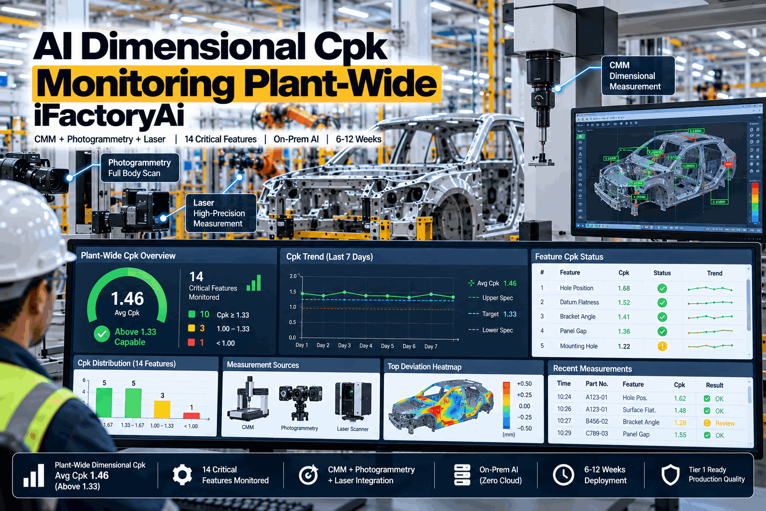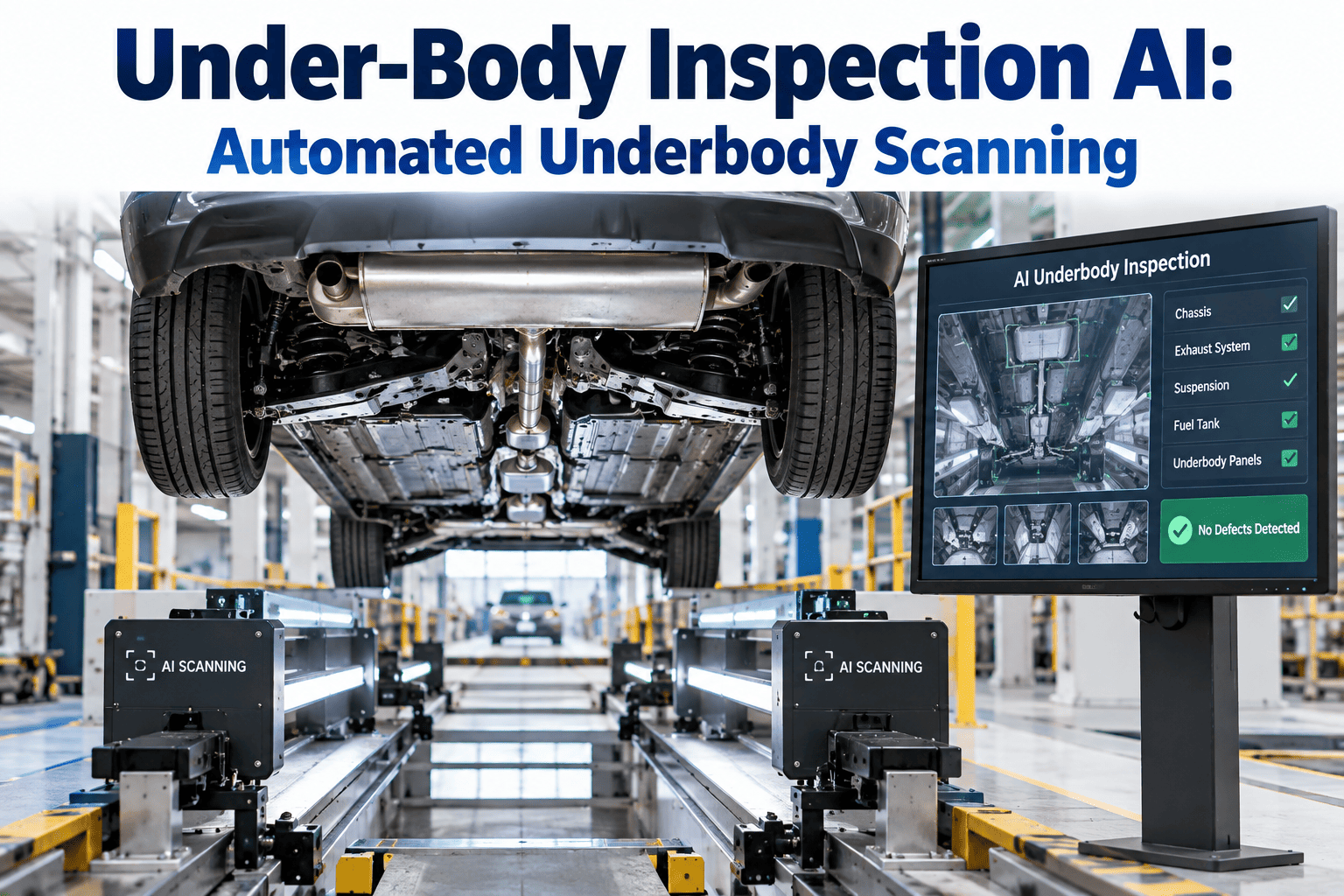
A body-in-white shell moves through the line every sixty to ninety seconds, and every one of those shells is carrying hundreds of dimensional features that either sit inside tolerance or start a warranty claim two years from now. Offline CMM rooms were built for a slower era of manufacturing, where checking a handful of parts per shift was considered thorough quality control. That assumption no longer holds on a modern high-volume line, where a single missed warp or a drifting GD&T callout can propagate through hundreds of units before a batch sample ever catches it. Inline 3D dimensional metrology closes that gap by measuring geometry at the same speed the line moves, turning a once-a-shift audit into a real-time verification of every single part. Manufacturers evaluating Book a Demo with iFactory to see how AI-driven 3D scanning validates dimensional accuracy without slowing the line down.
Why Offline CMM Checks Cannot Keep Up With 60–90 Cars an Hour
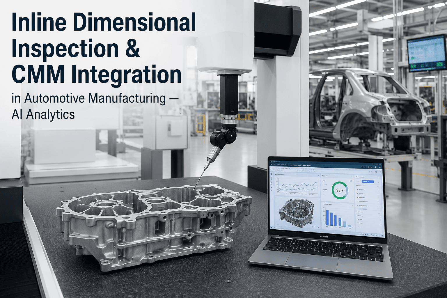
A coordinate measuring machine delivers excellent accuracy, but it was never designed to operate at the pace of a modern assembly line. Parts are pulled from the line, carried to a climate-controlled room, fixtured by hand, and probed point by point — a process that can take hours for a single body shell carrying hundreds of critical dimensions. By the time the report comes back, the line has already built dozens or hundreds more units using the exact same process settings. If that process has drifted, every one of those units carries the same undetected deviation.
The consequence is not a rare edge case — it is a structural limitation of batch sampling itself. A plant checking one part per hour on a line producing seventy-five cars an hour is inspecting roughly one percent of production. The other ninety-nine percent ship on trust. Inline 3D scanning removes that gap entirely by measuring dimensional geometry on the part as it moves through the station, comparing captured point-cloud data against the CAD reference in near real time, and flagging deviations before the next station ever sees the part.
Four Places Inline 3D Metrology Pays for Itself Fastest
Not every station needs full-surface scanning on day one. Manufacturers get the fastest return by targeting the stations where dimensional drift is most common and most expensive to catch late. The four use cases below represent the highest-value starting points for a phased inline metrology rollout.
Body-in-White Warp & Twist
Thermal distortion from welding sequences causes panel warp that a fixture check alone will not reveal. Full-surface point-cloud capture measures warp and twist across the entire shell against the nominal CAD model, station by station.
GD&T Callout Validation
Flatness, profile, position, and true position callouts are validated automatically against the engineering model, replacing manual gauge checks that only sample a handful of the callouts on the drawing.
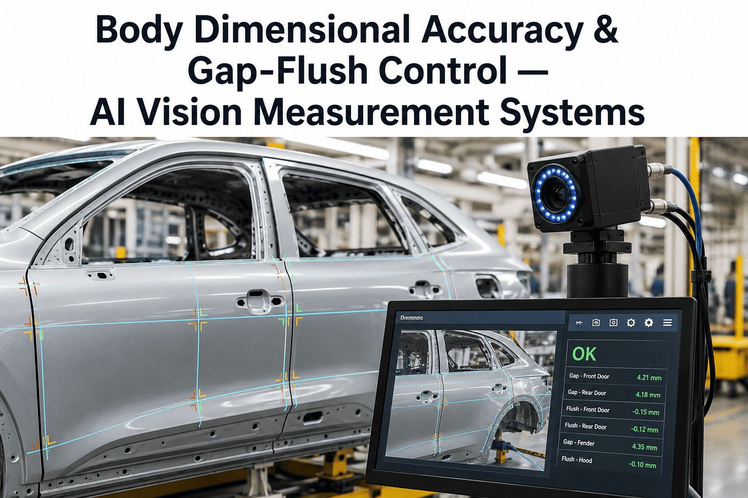
Closure Panel Fit & Gap
Door, hood, and hatch fit-and-flush is measured continuously rather than spot-checked, catching hinge and striker drift long before it becomes a visible panel gap on the finished vehicle.
Fixture & Tooling Drift
Because every part is measured, systemic drift in a jig or fixture shows up as a trend across dozens of consecutive units, not as a single anomalous CMM report discovered days later.
From Point Cloud to Pass/Fail Decision in One Station Cycle
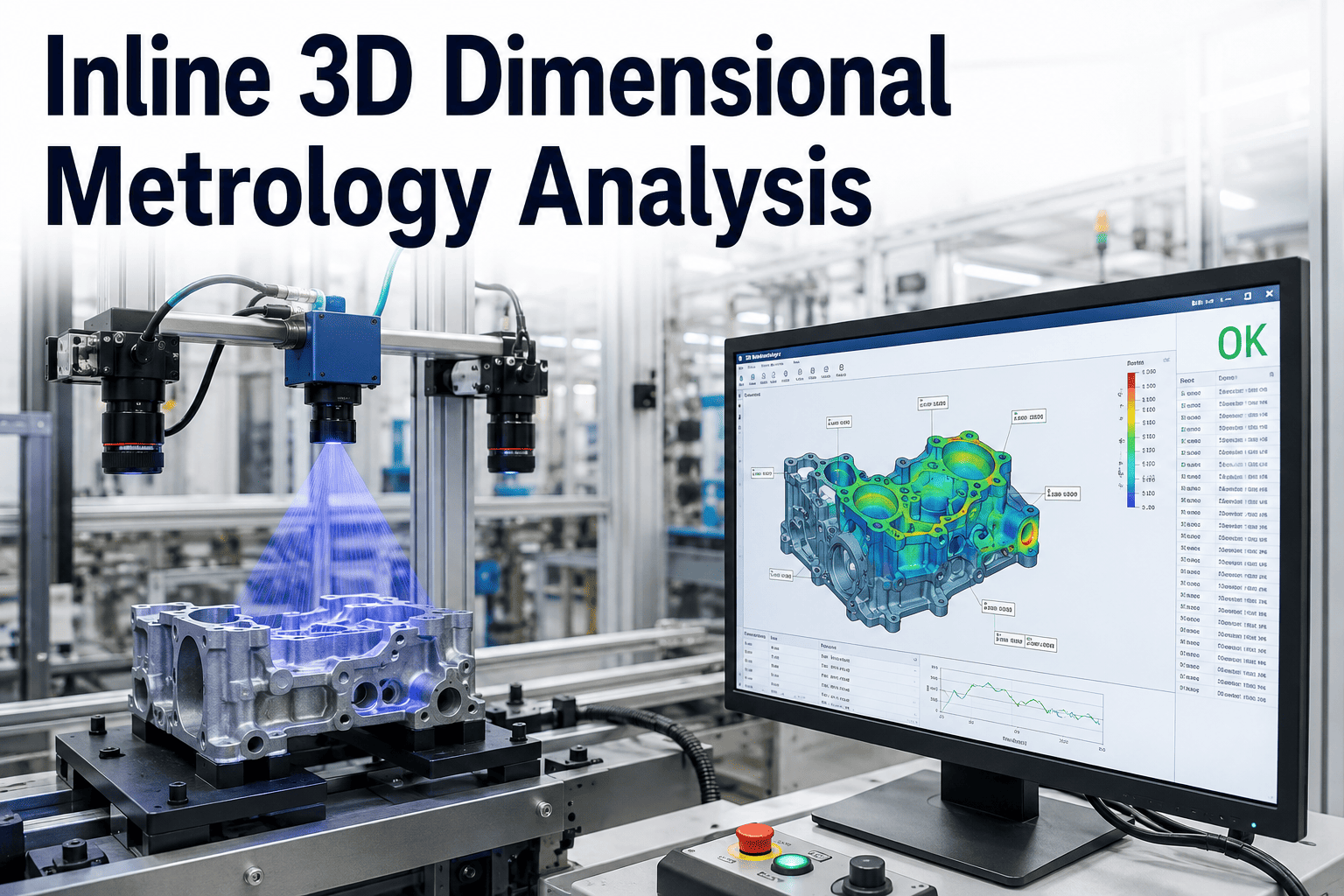
Inline 3D dimensional metrology combines structured-light or laser scanning hardware with AI-driven alignment and deviation analysis. The system captures a dense point cloud of the part, aligns it to the nominal CAD reference using digital twin alignment techniques, and calculates deviation across every measured feature — all inside the normal station cycle time, without pausing the line or pulling the part off its carrier.
Capture
Structured-light or laser sensors mounted at the station capture a full 3D point cloud of the part surface as it arrives, without contact and without interrupting carrier movement.
Align
AI alignment algorithms register the captured point cloud against the nominal CAD model, compensating for part positioning variation so every measurement is taken from a consistent reference frame.
Measure
Every programmed GD&T callout, warp zone, and critical-to-quality feature is measured simultaneously against tolerance, producing a full deviation map rather than a handful of sampled points.
Decide
Pass/fail decisions, deviation heatmaps, and trend data are pushed to the line PLC and quality dashboard within the station cycle time, so out-of-tolerance parts are flagged before the next operation.
Offline CMM vs. Inline 3D AI Metrology
The table below lays out the practical differences plant quality teams experience once inline scanning replaces or supplements offline CMM sampling on a high-volume line.
| Factor | Offline CMM Sampling | Inline 3D AI Metrology |
|---|---|---|
| Coverage | 1–2% of parts, sampled per shift | 100% of parts, every cycle |
| Feedback time | Hours, sometimes next shift | Within station cycle time |
| Features measured | Limited set per fixture setup | Full surface, hundreds of features |
| Drift detection | Delayed, batch-level | Immediate, part-by-part trending |
| Line impact | Parts removed from line | Measured in motion, no removal |
| Documentation | Manual report per sample | Automatic record for every unit |
Getting From Pilot Station to Full Line Coverage
Manufacturers rarely convert an entire line to inline metrology in one step, and they should not. A phased rollout builds confidence in the deviation data, validates the alignment accuracy against known CMM baselines, and gives the quality team time to tune tolerance thresholds before scaling coverage across every station.
Baseline & Pilot Station
CAD models are loaded, one high-value station is instrumented, and captured data is cross-validated against existing CMM measurements to confirm sub-millimeter alignment accuracy.
PLC Integration & Threshold Tuning
Pass/fail thresholds are tuned against real production variation, and deviation data is connected directly to the line PLC so out-of-tolerance parts trigger an automated response.
Multi-Station Rollout
Coverage expands to additional stations across the body shop, with trend dashboards aggregating deviation data across the full line to identify systemic tooling drift.
What Quality Teams Report After Switching to Inline Scanning
Of parts measured against a fraction sampled under offline CMM programs, closing the blind spot between quality checks.
Statistical confidence achieved on critical GD&T features when AI alignment is validated against a known CAD reference.
From part capture to deviation report, compared to hours for a batch CMM report to return to the line.
Line stoppage required, since parts are measured in motion rather than pulled and fixtured offline.
Inline 3D Dimensional Metrology — Common Questions
How accurate is inline 3D scanning compared to a CMM?
Modern structured-light and laser inline systems achieve sub-millimeter accuracy when properly calibrated and aligned against the CAD reference, matching CMM-grade results on the features that matter most for production tolerance decisions. The gap that remains is measured in microns for most automotive body applications, not in millimeters, and it continues to close as sensor resolution and AI alignment models improve. For applications requiring traceable sub-ten-micron accuracy, such as aerospace tolerancing, a CMM room still has a role — but for the vast majority of production dimensional checks, inline scanning meets the requirement inside the cycle time. Teams considering a switch can Book a Demo to see live accuracy validation on their own parts.
Does inline metrology replace the CMM room entirely?
Most manufacturers run both in parallel rather than eliminating the CMM room outright. Inline scanning covers 100% of parts for the features that drive the majority of quality escapes, while the CMM room remains available for engineering-grade root cause investigations, first-article inspection, and any feature that contractually requires traceable CMM certification. Over time, as confidence in the inline data grows, many plants shift the CMM room from a production gate to a support and audit function.
What happens when the system flags an out-of-tolerance part?
The deviation report and heatmap are pushed to the line PLC and quality dashboard within the station cycle, triggering whatever workflow the plant defines — an automated hold, an operator alert, or a routing change that sends the part to a rework station. Every flagged part carries a full deviation record, so the quality team can review exactly which features were out of tolerance and by how much, rather than relying on a binary pass or fail.
How long does it take to instrument a new station?
A single pilot station is typically instrumented and validated against existing CMM baselines within two to three weeks, including sensor mounting, CAD model loading, and initial threshold calibration. Full multi-station rollout across a body shop generally completes within twelve to sixteen weeks, depending on the number of stations and the complexity of the part geometry being measured. Support is available throughout the rollout at iFactory Support.
Can inline metrology detect fixture and tooling drift over time?
Yes, and this is one of its highest-value applications. Because every part is measured rather than a small sample, systemic drift in a jig, fixture, or robot path shows up as a clear trend across consecutive units on the trend dashboard, often days or weeks before it would surface in an offline CMM audit. Quality engineers can trace the trend back to a specific station and schedule preventive maintenance before the drift produces a defect.