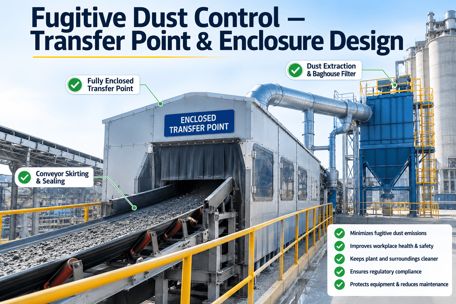
Walk the transfer points on almost any cement plant and you can usually spot the fugitive dust problem before you reach the control room data. It settles on structural steel, drifts across walkways, and collects in drifts near belt transfers, elevator boots, and mill discharge chutes. Environmental teams chase it with sweeping schedules and suppression sprays, but the real fix rarely starts with cleanup. It starts with the enclosure design at the point where dust actually escapes. Book a Demo with iFactory AI to see how engineered enclosure and extraction design closes the gap that housekeeping alone can never fully solve.
Fugitive Dust Is an Enclosure Problem Before It Is a Cleanup Problem.
iFactory AI helps cement plants engineer transfer point enclosures, dust curtains, and extraction hoods that stop dust at the source instead of managing it after it escapes.
The Physics Behind Fugitive Dust at Material Transfer Points
Every time bulk material drops from one conveyor to another, from a bucket elevator into a boot, or from a mill into a discharge chute, it displaces a volume of air roughly equal to the material's own volume. That displaced air, known as induced air, has to go somewhere, and if the enclosure around the transfer point is not engineered to manage it, the air escapes through whatever gap it can find, carrying fine dust particles with it. This is why dust control at a transfer point is fundamentally an air management problem, not just a containment problem. An enclosure that looks sealed but has not accounted for induced air volume will still leak dust under pressure, often at the exact seams and access doors that were installed to keep it contained.
The severity of the problem scales directly with drop height, material velocity, and particle fineness, three variables that are common at cement plants specifically because raw meal, clinker dust, and cement itself are all extremely fine materials moved at high volumes across tall transfer chutes. A transfer point that would generate negligible dust with coarse aggregate can generate a visible plume with cement dust falling the same distance, which is why generic industrial dust containment approaches often underperform when applied directly to cement material handling without adjustment for particle characteristics.
Bulk elbows and elevator boots add a second dust generation mechanism beyond the free-fall drop itself, since these transition points also introduce turbulence as material changes direction sharply, agitating fine particles that a straight drop would not disturb to the same degree. This is why an elevator boot, despite handling the same material as a straight conveyor transfer nearby, often requires a different enclosure and extraction strategy tuned to its specific turbulence pattern rather than simply replicating a design that worked well on a straight-drop transfer point elsewhere in the plant.
Four Zones Where Enclosure Design Actually Matters
Effective enclosure design treats a transfer point as a sequence of distinct zones, each with a different dust generation mechanism and a different engineering response required to control it.
Loading Zone
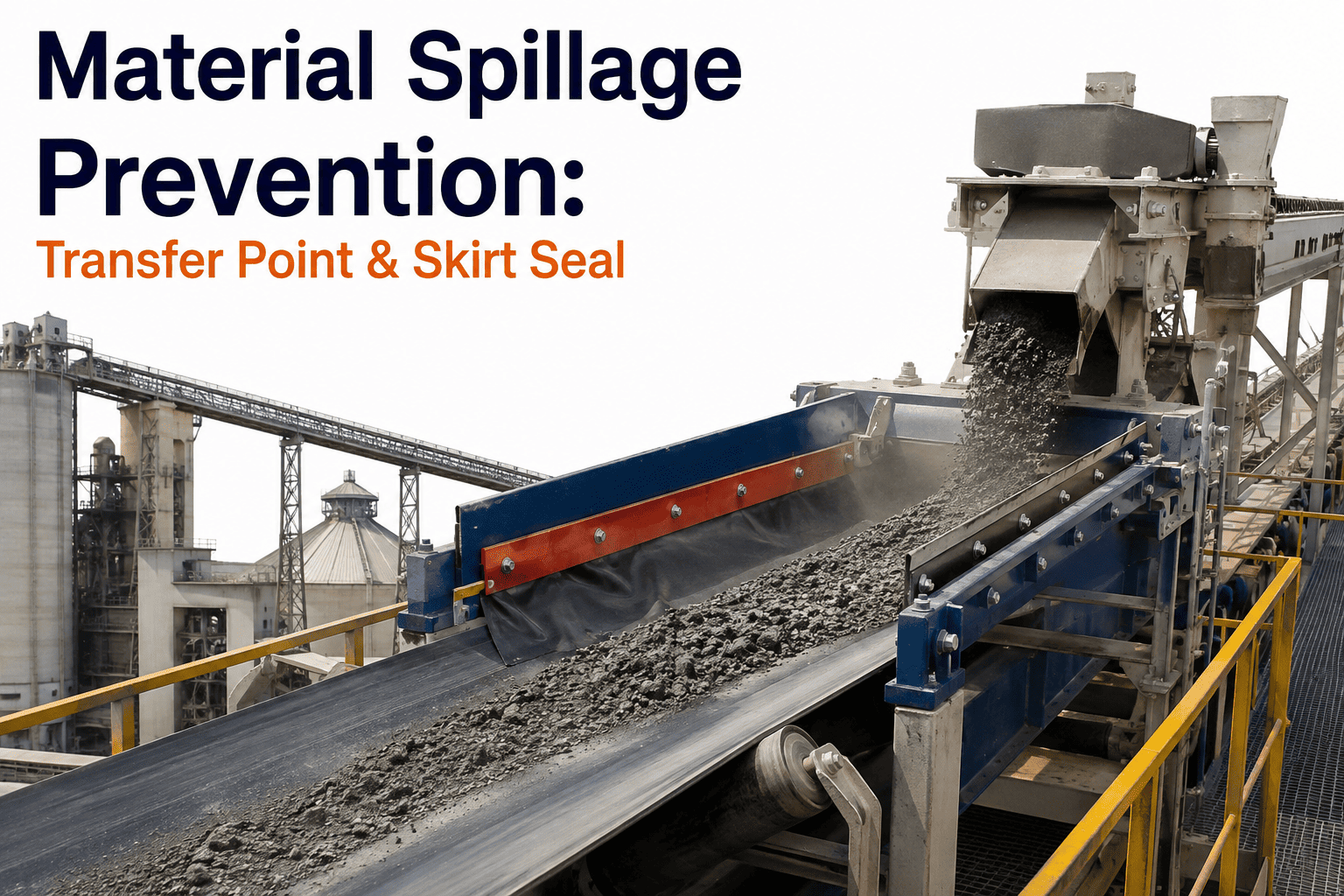
Where material first contacts the receiving conveyor. Impact and material spread generate the highest dust volume here, requiring a fully enclosed skirtboard with correctly sealed rubber skirting along the belt edges.
Settling Zone
The extended enclosure beyond the loading zone where induced air velocity needs to drop below the point where it can carry dust back out through skirtboard seals, typically requiring additional enclosure length calculated from belt speed.
Transition Zone
Where the enclosure narrows back toward the open belt run. Poorly designed transitions create pressure differentials that pull dust-laden air out through gaps, making tapered transition geometry a critical but often overlooked detail.
Extraction Zone
The point where an extraction hood connects to a dust collection system, removing the induced air volume before it can find its own way out through the enclosure's weakest point.
Why One Enclosure Design Does Not Fit Every Material
Cement plants move three distinct material types through transfer points that behave very differently under the same enclosure design, and treating them identically is one of the more common reasons a retrofit underperforms its target. Moisture content, particle size distribution, and bulk density each change how material falls, how much air it displaces, and how far fine particles travel once airborne, which means the enclosure and extraction approach that works well for one material can be undersized or oversized for another running through an identical chute geometry.
High Fineness, Variable Moisture
Raw meal fineness combined with variable moisture from upstream drying creates inconsistent dust generation, requiring extraction sized for the driest expected condition rather than an average moisture assumption.
High Temperature, Abrasive
Clinker transfer points run hotter and the material is more abrasive, meaning enclosure materials and skirting need heat and wear resistance rated well beyond what raw meal or finished cement points require.
Extremely Fine, Free-Flowing
Finished cement is the finest and most free-flowing material in the plant, generating the highest induced air volume per ton transferred and demanding the tightest enclosure sealing tolerances of any material handling point.
A retrofit program that applies a single generic extraction sizing standard across raw meal, clinker, and finished cement transfer points will almost always leave at least one of those three material types under-controlled. iFactory AI's engineering process calculates induced air volume and extraction requirements separately for each material type present at a given transfer point, including accounting for the specific temperature and abrasion conditions that affect not just extraction sizing but also which enclosure and skirting materials will hold up over time in that particular location.
Sealed Enclosure vs. Open Chute: What the Data Shows
Plants that retrofit open or partially enclosed transfer chutes into properly engineered, extracted enclosures consistently see measurable reductions in ambient dust readings, not just at the transfer point itself but across the surrounding work area, since airborne fine particulate travels well beyond its point of origin before settling.
| Design Element | Open or Partial Chute | Engineered Sealed Enclosure |
|---|---|---|
| Skirtboard sealing | Rigid or absent rubber skirting | Adjustable multi-layer sealing rated for belt wear |
| Induced air handling | No dedicated extraction | Sized extraction hood matched to displaced air volume |
| Settling zone length | Minimal or none | Calculated from belt speed and drop height |
| Access doors | Often left open for inspection | Gasketed, self-closing with viewing ports |
| Ambient dust impact | Elevated readings 15+ meters away | Contained within enclosure footprint |
Sizing an Extraction Hood Correctly the First Time
The single most common failure in retrofit dust control projects is an extraction hood sized on a rule of thumb rather than the actual induced air volume of the specific transfer point it serves. Undersized extraction leaves excess induced air to escape through enclosure gaps regardless of how well those gaps are sealed, while oversized extraction wastes energy and can actually pull ambient dust back into the enclosure from adjacent open areas, creating a different fugitive dust source entirely.
Correct sizing starts with calculating induced air volume from material drop height, belt width, and material bulk density, then adding a safety margin for enclosure leakage that even a well-sealed system will have. iFactory AI's engineering process models each transfer point's specific geometry and material characteristics rather than applying a generic capture velocity standard across every point in the plant, which is why retrofits based on this approach typically achieve target dust reduction without the repeated hood resizing that generic sizing methods often require after initial installation.
Where Flexible Curtains Belong in a Dust Control Design
Rigid enclosure panels solve most of a transfer point's containment need, but certain locations require a flexible solution instead, particularly at points where equipment access, belt tracking movement, or irregular material geometry makes a fully rigid enclosure impractical. Dust curtain systems, layered strips of wear-resistant rubber or PVC hung across an opening, fill this gap by allowing material and equipment to pass through while still restricting the escape path for induced air and airborne dust.
The design detail that separates an effective curtain installation from an ineffective one is overlap and staggering. A single layer of curtain strips with gaps between them provides minimal containment, while a properly staggered double or triple layer, with each layer's gaps offset from the layer behind it, creates an effective barrier without fully blocking material flow or requiring the curtain to flex excessively during each pass. Curtain material selection also matters more than it might appear: standard PVC degrades quickly against the abrasive, alkaline dust common in cement handling, while wear-resistant rubber compounds rated for this specific environment maintain their sealing effectiveness far longer between replacement cycles.
Why Enclosure Effectiveness Degrades Without a Maintenance Plan
An enclosure that performs well at commissioning does not stay that way indefinitely without deliberate upkeep. Rubber skirting wears from continuous belt contact and needs periodic adjustment or replacement as it thins. Curtain strips crack and lose flexibility with age and abrasive exposure, eventually leaving gaps that reopen the escape paths the original installation closed. Access door gaskets compress and lose their seal over repeated openings. Each of these wear points is individually minor, but left unaddressed they compound, and a plant that invested in a well-engineered enclosure two years ago can find itself back to near-original dust levels without anyone having consciously decided to let that happen.
A practical inspection cadence catches this degradation before it becomes visible as ambient dust again. Skirtboard sealing and curtain condition are best checked on a monthly walk-through, since these are the highest-wear components and the ones most likely to show early signs of gap formation. Extraction hood static pressure is worth logging on a similar cadence, since a drop in static pressure at a given hood often indicates a partial duct blockage or fan performance issue well before the enclosure itself shows visible dust escape. Building these checks into an existing preventive maintenance schedule, rather than treating dust control as a separate program, is what keeps a retrofit's initial performance from quietly eroding over its first few years in service.
What Plants Report After Transfer Point Retrofits
Reduction in ambient dust readings near retrofitted transfer points
Drop in housekeeping labor hours spent on dust cleanup
Typical payback period from reduced material loss and labor
Prioritizing Transfer Points for Retrofit
Most cement plants have more transfer points needing attention than budget to address them all at once, which makes prioritization a critical first step. The highest-value retrofits are typically found by cross-referencing visible dust conditions against material throughput and particle fineness at each point, since a high-volume fine-material transfer point generates far more environmental and material loss impact than a low-volume coarse-material one, even if both look similarly dusty on a casual walkthrough. Plants that prioritize based on this combined view, rather than simply fixing the most visibly dusty points first, typically capture the majority of achievable dust reduction from a fraction of the total transfer points in the facility, making a phased retrofit program both financially and operationally practical.
Fugitive Dust Control at Transfer Points — Common Questions
What is the difference between dust suppression and dust containment?
Dust suppression uses water or chemical agents to bind dust particles and prevent them from becoming airborne in the first place, while containment relies on physical enclosures and extraction to capture dust that has already been generated. The most effective transfer point programs typically combine both, using enclosure design as the primary control and suppression as a secondary measure for material properties that enclosure alone cannot fully address. Our team can help determine the right combination for your specific material handling points.
How is extraction hood capacity actually calculated?
Extraction capacity is calculated from the induced air volume generated by the falling material stream, which depends on drop height, material bulk density, belt speed, and belt width, plus an additional margin for enclosure leakage. Generic capture velocity rules of thumb often under- or oversize hoods because they do not account for the specific geometry of each individual transfer point.
Can existing enclosures be retrofitted or do they need full replacement?
Most existing enclosures can be retrofitted rather than replaced entirely, particularly when the structural steel and general chute geometry are sound. Retrofits typically focus on improved skirtboard sealing, extended settling zone length, properly sized extraction connections, and gasketed access doors, all of which can usually be added to an existing structure without a full rebuild.
How do you prioritize which transfer points to fix first?
Prioritization should combine visible dust severity with material throughput and particle fineness at each point, since high-volume fine-material transfer points generate disproportionately more dust impact than their visual appearance alone might suggest. A structured audit across all transfer points typically identifies a smaller subset responsible for most of the plant's total fugitive dust burden.
Does dust control retrofit work require production downtime?
Most enclosure and extraction retrofits can be scheduled during planned maintenance windows rather than requiring dedicated production downtime, since the work is localized to individual transfer points rather than the full material handling line. Book a Demo to discuss scheduling around your plant's existing maintenance calendar.
Get an Engineered Look at Your Highest-Impact Transfer Points
Bring your plant's transfer point layout and let our team identify where enclosure and extraction design would deliver the fastest dust reduction.