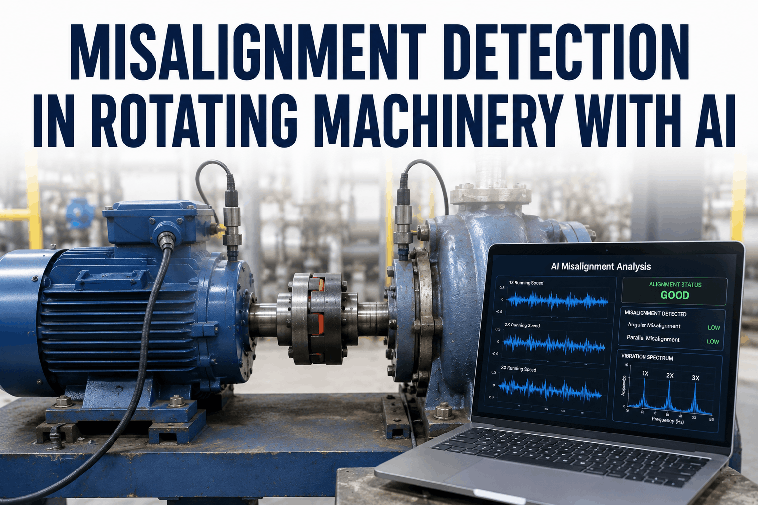
AI detects angular and parallel misalignment from vibration patterns at 1X, 2X, and 3X running speed — providing early warning of premature bearing and coupling failures across all rotating assets before misalignment-induced wear progresses to component damage. Start Trial Free to see how iFactory gives rotating equipment engineers the misalignment-specific vibration analysis needed to identify shaft alignment problems before bearing or coupling replacement becomes necessary.
Detect Angular and Parallel Misalignment Before Bearing and Coupling Failure
iFactory analyzes 1X, 2X, and 3X vibration harmonics with phase relationships and axial-to-radial ratios to classify misalignment type, severity, and direction — giving maintenance engineers actionable alignment correction data before component damage accelerates.
Why Misalignment Remains the Leading Cause of Premature Bearing Failure
Misalignment is estimated to contribute to 50% of rotating equipment failures in industrial facilities — yet most facilities have no continuous misalignment monitoring between scheduled alignment checks, which occur months apart. A machine that was precision-aligned during a shutdown can develop misalignment within weeks from thermal growth, pipe strain changes, foundation settlement, or soft foot progression. By the time the next scheduled alignment check occurs, bearing wear from sustained misalignment loading may already be advanced. AI vibration analysis trained on misalignment-specific spectral and phase signatures provides continuous misalignment monitoring between alignment checks — detecting the onset of problematic misalignment while correction is still a maintenance planning decision rather than an emergency bearing replacement. Engineering teams that Book a Demo with iFactory see how continuous misalignment monitoring changes bearing replacement frequency across rotating equipment populations.
-
Angular Misalignment Detection
iFactory identifies angular misalignment through dominant 1X vibration with high axial component and 180-degree phase reversal across the coupling — the spectral and phase signature that distinguishes angular from parallel misalignment for targeted correction.
-
Parallel Misalignment Detection
Parallel misalignment produces dominant 2X vibration relative to 1X, with radial phase differences of approximately 180 degrees across the coupling. iFactory tracks the 2X-to-1X ratio and radial phase relationships to classify parallel offset severity.
-
Combined Misalignment Classification
Most real-world misalignment conditions combine angular and parallel components. iFactory classifies the dominant misalignment type and its directional orientation — providing the specific correction vector that alignment technicians need without trial-and-error shim adjustment.
-
Thermal Growth Compensation
Machines that operate at elevated temperatures grow from cold alignment to hot running position. iFactory tracks vibration signature changes from startup to steady state — identifying thermal misalignment that develops after initial cold alignment and requires operating temperature correction factors.
-
Soft Foot Detection
Soft foot — uneven machine foot contact with the baseplate — produces characteristic changes in the misalignment signature when hold-down bolts are tightened. iFactory flags spectral patterns consistent with soft foot for investigation before precision alignment is attempted.
-
Coupling Wear Differentiation
Worn couplings produce vibration signatures that overlap with misalignment — particularly at 2X running speed. iFactory distinguishes coupling wear from misalignment using phase relationship analysis and coupling-type-specific spectral characteristics to prevent misdiagnosis.
Misalignment Vibration Signature Analysis: Key Indicators
-
1X Axial Dominance and Phase Reversal: Angular Misalignment Signature
Primary IndicatorAngular misalignment produces a vibration signature characterized by high 1X amplitude in the axial direction — often equal to or exceeding the radial 1X component — and a phase difference of approximately 180 degrees between axial measurements taken on opposite sides of the coupling. The axial-to-radial 1X ratio and the coupling phase reversal together form the most reliable angular misalignment fingerprint in the vibration spectrum. iFactory extracts axial 1X amplitude ratios and phase differences from multi-channel vibration data — automatically flagging configurations where the axial-to-radial ratio exceeds 0.5 and the coupling phase reversal exceeds 150 degrees as probable angular misalignment requiring correction. ISO 10816 vibration severity classifications apply to the resulting vibration amplitudes, and iFactory reports misalignment severity against these standards. Teams that Start Trial can begin monitoring axial-to-radial 1X ratios across installed sensor positions immediately.
Spectral Feature
1X axial dominant, axial-to-radial ratio >0.5
Phase Indicator
~180° phase reversal across coupling in axial direction
iFactory Record
Axial ratio and phase difference tracked per machine train
-
2X Radial Dominance and 180-Degree Radial Phase: Parallel Misalignment
Offset IndicatorParallel offset misalignment excites the 2X running speed harmonic predominantly in the radial direction — producing a 2X-to-1X amplitude ratio typically greater than 0.5 and often approaching or exceeding 1:1 in severe cases. The phase difference between radial measurements on drive and driven sides of the coupling approaches 180 degrees when parallel misalignment is the dominant condition. iFactory monitors 2X radial amplitude relative to 1X, computes the coupling radial phase differential, and applies classification logic based on ISO 10816 vibration standards to grade parallel misalignment severity. For flexible couplings, the 3X harmonic may also be elevated — iFactory tracks 3X radial amplitude as a secondary parallel misalignment indicator for coupling types where this harmonic is diagnostically significant. Teams that Book a Demo can review how iFactory's 2X tracking is configured for different coupling types in their equipment population.
Spectral Feature
2X radial dominant, 2X/1X ratio >0.5
Phase Indicator
~180° radial phase difference across coupling
iFactory Record
2X/1X ratio trend and coupling phase differential per machine
-
3X Harmonic Elevation: Rigid Coupling and Severe Combined Misalignment
Severity AmplifierThe 3X running speed harmonic becomes diagnostically significant in two specific misalignment contexts: rigid or gear-type couplings where 3X is the primary misalignment response frequency, and severe combined angular-plus-parallel misalignment where higher-order harmonics develop as the coupling compensates for large offset. iFactory tracks 3X harmonic amplitude alongside 1X and 2X — using the three-harmonic pattern and their mutual amplitude relationships to classify misalignment type and estimate severity beyond what 2X alone can indicate. In rigid coupling machine trains, iFactory's 3X analysis is particularly valuable because the absence of coupling flexibility means misalignment loads transmit directly to bearings without the spectral damping that flexible couplings provide.
Spectral Feature
3X elevation in rigid couplings or severe combined misalignment
Coupling Relevance
Most diagnostic in rigid and gear-type coupling configurations
iFactory Record
1X/2X/3X harmonic pattern tracked per coupling type
-
Bearing Defect Frequency Acceleration: Misalignment-Induced Failure Progression
Consequence TrackingSustained misalignment applies non-uniform radial loading to rolling element bearings — accelerating defect frequency development on the loaded race and rolling elements. iFactory tracks bearing defect frequencies (BPFO, BPFI, BSF, FTF) in parallel with misalignment indicators — enabling simultaneous assessment of misalignment severity and its resulting bearing damage progression. When iFactory detects both elevated 2X misalignment signature and developing BPFO amplitude on the same machine, the combination provides a more urgent priority signal than either indicator in isolation — the misalignment has already caused bearing damage that will progress even if alignment is corrected. Teams that Start Trial can configure combined misalignment-plus-bearing defect alerts for priority machine trains.
Defect Frequencies
BPFO, BPFI, BSF, FTF tracked alongside misalignment indicators
Combined Alert
Concurrent misalignment + bearing defect triggers urgent priority
iFactory Record
Bearing defect frequency trend correlated to misalignment history
-
Thermal Growth Tracking: Hot Alignment Verification
Operating State AnalysisMachines aligned cold at ambient temperature operate in a different alignment state at operating temperature due to differential thermal expansion of machine feet, bearing housings, and connected piping. iFactory tracks the evolution of misalignment indicators from cold start through thermal steady state — identifying machines where cold alignment is acceptable but thermal growth produces misalignment at operating temperature. This thermal growth tracking enables reliability engineers to calculate the operating temperature correction offsets needed to achieve alignment at running conditions — a calculation that previously required either hot alignment checks (operationally disruptive) or estimated correction factors from published thermal growth data. Teams that Book a Demo can review thermal growth tracking configuration for their specific machine types.
Tracking Period
Cold start to thermal steady state per machine startup
Analysis Output
Cold-to-hot misalignment delta and correction offset estimate
iFactory Record
Thermal growth signature archived per machine startup event
-
Pipe Strain and Foundation Settling: External Misalignment Sources
Root Cause TrackingMisalignment that recurs shortly after precision alignment correction is frequently caused by external forces — pipe strain from connected process piping imposing loads on pump nozzles, foundation settling changing machine foot positions, or thermal cycling of connected equipment altering load paths. iFactory tracks misalignment indicator trends across multiple alignment cycles — flagging machines where misalignment returns within a defined period after correction as candidates for external load investigation. This recurrence pattern analysis distinguishes equipment with alignment retention problems from equipment where the alignment procedure was not correctly executed, directing engineering attention to the structural or piping root cause rather than repeated realignment. Teams that Start Trial can configure recurrence tracking for machine trains with a history of rapid realignment requirements.
Recurrence Signal
Misalignment indicators returning within configurable post-correction window
Root Cause Flags
Pipe strain, soft foot, foundation settling pattern recognition
iFactory Record
Alignment correction history and recurrence interval tracked per machine
Misalignment Detection Performance Indicators
Misalignment Detection Lead Time
AI phase and harmonic analysis detects misalignment 52 days before bearing failure versus 0 average lead time for scheduled alignment checks that occur between events.
Classification Accuracy by Misalignment Type
iFactory achieves 93% classification accuracy for angular misalignment and 91% for parallel — enabling type-specific correction without additional diagnostic tests.
Bearing Life Extension from Early Detection
Early misalignment correction based on AI detection recovers 70% of bearing service life that would be consumed by sustained misalignment loading before a conventional alarm.
Misalignment Recurrence Reduction
Continuous AI misalignment monitoring reduces fleet-wide realignment frequency from 8.2 per quarter to 1.8 by identifying and addressing root causes rather than repeating symptom correction.
Misalignment Detection Reference: Vibration Signature Specifications
Scroll for more
| Misalignment Type | Primary Spectral Feature | Phase Indicator | ISO 10816 Reference | Corrective Action |
|---|---|---|---|---|
| Angular Misalignment | 1X dominant, high axial component | ~180° axial phase across coupling | Zone C/D amplitude at 1X | Angular correction — shim under foot |
| Parallel Misalignment | 2X dominant radial, 2X/1X >0.5 | ~180° radial phase across coupling | Zone C/D at 2X | Parallel offset — lateral machine movement |
| Combined Misalignment | Elevated 1X, 2X, and 3X | Mixed axial and radial phase | Zone D at multiple harmonics | Combined angular and offset correction |
| Thermal Misalignment | Misalignment signature at operating temp only | Phase shift from cold to hot state | Zone B cold, Zone C/D hot | Cold alignment with thermal offset correction |
| Soft Foot | Changes in 1X on bolt tighten/loosen | Phase changes with foot loading | Variable — foot-dependent | Correct foot contact before alignment |
How iFactory Supports Continuous Misalignment Monitoring
Precision alignment performed during shutdowns is only effective as long as alignment conditions are maintained — and in operating industrial facilities, thermal cycling, process load changes, pipe strain, and foundation movement mean that alignment degrades continuously between checks. iFactory provides the continuous monitoring layer that scheduled alignment checks cannot: analyzing 1X, 2X, and 3X harmonic amplitudes with phase relationships across machine trains, classifying detected misalignment by type and direction, and estimating severity against ISO 10816 standards — giving reliability engineers the misalignment intelligence to schedule corrective alignment before bearing damage accumulates. When iFactory detects a developing parallel misalignment condition on a critical pump train, quantifies severity as approaching ISO Zone C, and identifies that the 2X-to-1X ratio has been increasing for three weeks, the maintenance planning team has the data to schedule alignment correction at the next planned opportunity rather than waiting for a forced outage. Facilities can Start Trial and begin continuous misalignment monitoring on priority machine trains from their first iFactory configuration session.
Harmonic Amplitude Tracking
iFactory tracks 1X, 2X, and 3X running speed amplitudes in both axial and radial directions per machine train — providing the harmonic pattern data that misalignment classification requires beyond what single-frequency alarms can deliver.
Phase Relationship Analysis
iFactory computes phase differences between measurement points across couplings — providing the angular and radial phase indicators that distinguish angular from parallel misalignment and confirm classification accuracy.
ISO 10816 Severity Grading
iFactory grades detected misalignment severity against ISO 10816 vibration standards — providing compliance-referenced severity classifications that support maintenance priority decisions and regulatory reporting.
Alignment Recurrence Pattern Analysis
iFactory tracks misalignment indicator history across alignment correction events — identifying machines where misalignment recurs rapidly for external load investigation and root cause resolution.
Deploying Continuous Misalignment Monitoring: Implementation Steps
01
Identify Priority Machine Trains for Monitoring
Select machine trains with high bearing replacement frequency, a history of alignment-related failures, or recent alignment corrections — these represent the highest return targets for continuous misalignment monitoring deployment.
02
Verify Sensor Configuration for Phase Analysis
Confirm that vibration sensors are installed on both sides of the coupling in both axial and radial orientations — the phase analysis that distinguishes misalignment type requires measurements at drive-side and driven-side bearing housings with consistent angular reference.
03
Establish Post-Alignment Baseline Spectra
Run iFactory's baseline acquisition on each machine train immediately after a verified precision alignment — capturing the 1X/2X/3X harmonic profiles and phase relationships that represent the correctly aligned reference state.
04
Configure Misalignment Alert Thresholds by Machine Class
Define the 2X/1X ratio thresholds, axial-to-radial ratio limits, and phase differential ranges that trigger iFactory alerts for each machine class — referencing ISO 10816 zone boundaries for the specific machine size and type.
05
Integrate with Alignment Work Order Workflow
Configure iFactory to generate alignment work orders when misalignment indicators reach alert thresholds — pre-populating work orders with misalignment type classification, severity assessment, and directional correction data for the alignment technician.
06
Track Correction Effectiveness and Recurrence
Review post-alignment vibration spectra in iFactory to confirm correction effectiveness — and track machines where misalignment indicators return within the recurrence window for pipe strain or foundation investigation. Book a Demo to see the full misalignment monitoring workflow.
Frequently Asked Questions
How does AI detect misalignment from vibration data?
AI misalignment detection analyzes the amplitude ratios between 1X, 2X, and 3X running speed harmonics in axial and radial directions, combined with phase differences between measurements taken on opposite sides of the coupling — producing classification outputs that identify misalignment type and severity with accuracy that threshold-based alarms cannot match.
What vibration measurements are required for misalignment classification?
Accurate misalignment classification requires accelerometers on bearing housings on both sides of the coupling, in both axial and radial orientations, with a phase reference trigger. Radial-only measurements can detect 2X elevation associated with parallel misalignment but cannot reliably distinguish angular misalignment without the axial and phase data.
How does iFactory distinguish misalignment from other 2X vibration sources?
iFactory uses the phase relationship across the coupling as the primary discriminator — misalignment produces characteristic ~180° phase differences that resonance, looseness, and other 2X sources do not. Coupling type classification also adjusts the expected harmonic pattern so that coupling-specific responses are not misclassified as misalignment.
Can iFactory detect thermal misalignment that only occurs at operating temperature?
Yes. iFactory tracks misalignment indicators from cold start through thermal steady state — identifying cases where cold alignment is within tolerance but operating temperature thermal growth produces out-of-tolerance misalignment conditions at running speed and temperature.
What ISO standard does iFactory use for misalignment severity grading?
iFactory references ISO 10816 vibration severity zones for rotating machinery — classifying misalignment-induced vibration amplitudes against Zone A (new machines), Zone B (acceptable long-term operation), Zone C (acceptable short-term), and Zone D (damage risk) boundaries appropriate for each machine class and power rating.
Monitor Shaft Alignment Continuously — Not Just at Scheduled Checks
iFactory gives rotating equipment engineers continuous misalignment detection using 1X, 2X, and 3X harmonic analysis with phase relationships — identifying angular and parallel misalignment before bearing damage accumulates and scheduling alignment correction as a planned activity rather than an emergency response.