A PLC — programmable logic controller — is the hardware that sits between a building's physical systems and the people who manage them. In a university campus context, PLCs are the reason a chiller plant responds to occupancy, a fire alarm can trigger a stairwell pressurisation fan within milliseconds, and an HVAC zone switches to setback mode the moment a lecture ends. Most facilities staff interact with PLCs every day through building management system screens without knowing it. This guide explains what PLCs are, how they work in campus buildings, and what an analytics platform can do with the data they generate continuously. See how iFactory connects to your campus PLC infrastructure and turns that data into actionable intelligence — Book a Demo.
Understand what programmable logic controllers are, how they control every major building system on a university campus, and how connecting PLC data to an AI analytics platform closes the gap between raw sensor signals and actionable facility intelligence.
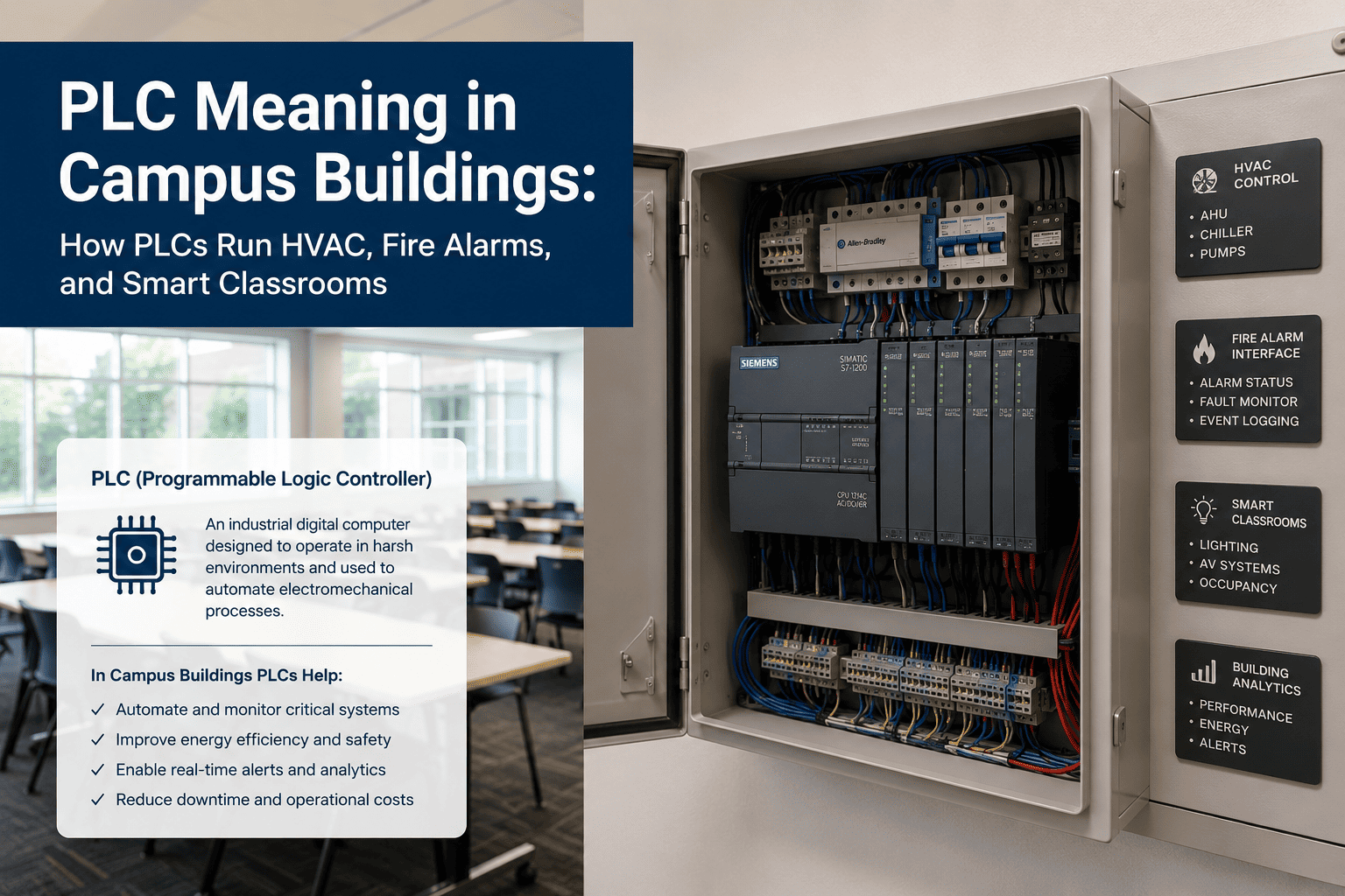
PLC Definition: What a Programmable Logic Controller Actually Is
A programmable logic controller is an industrial computer designed to monitor inputs from physical sensors — temperature probes, pressure transducers, occupancy detectors, flow meters, contact switches — and control physical outputs — valves, fans, pumps, dampers, lighting circuits, relays — based on a programmed set of logic rules. PLCs were originally developed for manufacturing environments in the late 1960s to replace large relay-based control panels. They are now the standard control hardware across industrial, commercial, and building automation applications worldwide.
The key characteristics that define a PLC and distinguish it from a general-purpose computer are its deterministic scan cycle, its hardened electrical design for industrial environments, and its ability to execute control logic reliably in real time regardless of what else is happening on connected networks. In a campus building context, these characteristics mean the HVAC system responds to a setpoint change in milliseconds, the fire suppression relay activates within a defined time window, and the chiller plant maintains leaving water temperature within specification continuously — not when a server has spare processing capacity.
How PLCs Are Programmed and How They Execute Control Logic
Understanding how a PLC processes information helps facilities staff interpret what they see on BMS screens and understand why a system behaves the way it does when conditions change. The PLC execution model is simple in principle — though the programs controlling a large campus chiller plant can contain thousands of rungs of logic.
At the start of each scan cycle — typically every 10 to 100 milliseconds — the PLC reads the current state of all physical inputs connected to its input modules: temperature sensor values, pressure readings, contact states from switches and relays, flow meter pulses, and occupancy detector outputs. These values are stored in the PLC's input image register — a snapshot of the physical world at that moment.
The PLC executes its control program from top to bottom, evaluating each instruction against the current input image. For HVAC systems this includes PID control loops that calculate valve positions from temperature error, sequencing logic that stages chillers on and off as load changes, and safety interlock logic that shuts down equipment if a measured parameter exceeds a protection threshold. The program does not wait for external input — it executes completely, every scan cycle.
At the end of each scan cycle, the PLC writes the results of program execution to its output modules — opening or closing valves, varying fan speed via variable frequency drives, switching relays, and sending setpoint commands to downstream controllers. Physical actuators respond to the output state within their own mechanical response times, which are typically much slower than the PLC scan cycle itself.
In parallel with its control function, the PLC makes its current tag values available to building management systems, SCADA platforms, and historian databases via communication protocols. This is the layer that analytics platforms like iFactory read from — continuously ingesting PLC register values to build the time-series dataset that drives fault detection, energy analytics, and predictive maintenance models.
How PLCs Control HVAC Systems in Campus Buildings
HVAC is the largest and most complex PLC application in most campus buildings. A single academic building may contain multiple air handling units, dozens of variable air volume boxes, a chilled water system, a heating hot water circuit, and a building exhaust system — each with its own PLC-based controller, all coordinated by a supervisory controller that manages the building as a system rather than as isolated pieces of equipment.
The AHU PLC manages supply fan speed via VFD, chilled water valve position, heating coil valve, outside air damper, and return air damper based on discharge air temperature setpoint, duct static pressure, and mixed air temperature. On occupied/unoccupied schedules, the PLC sequences the unit through pre-conditioning, occupied mode, and setback without manual intervention. The PLC also monitors filter differential pressure to flag when a filter service is due.
Each VAV box in a campus building has its own small PLC-based controller that positions the box damper to deliver the correct airflow to its zone based on the zone thermostat setpoint and occupancy input. In labs and seminar rooms with CO2 sensors, the VAV controller modulates airflow based on measured CO2 concentration to maintain air quality without over-conditioning unoccupied spaces. All VAV controllers report to the supervisory AHU controller.
Campus chiller plants are among the most complex PLC applications in building automation. The plant PLC sequences chillers on and off as cooling load changes, controls condenser water flow through cooling towers, manages chilled water pump staging, and trims chilled water supply temperature setpoint based on building load. Monitoring chiller plant PLC data — compressor suction and discharge pressure, leaving water temperature deviation, kW per ton — enables analytics platforms to detect efficiency degradation before it increases energy cost significantly.
Above individual equipment PLCs sits the building automation system supervisory controller — typically a Siemens Desigo, Honeywell EBI, Johnson Controls Metasys, or Schneider EcoStruxure system. This layer aggregates data from all building PLCs, provides the operator interface that facilities staff see on screen, implements scheduling and global setpoint strategies, and exposes the building's data to energy management and analytics platforms via BACnet or Modbus.
How PLCs Interface with Fire Alarm and Life Safety Systems
Fire alarm systems in campus buildings are not PLCs in the conventional sense — they are listed life safety panels that meet UL 864 and NFPA 72 requirements. However, the interface between fire alarm systems and building mechanical systems — stairwell pressurisation fans, smoke exhaust fans, HVAC shutdown sequences, elevator recall, and door hold-open release — is implemented through PLC-based BAS integration. Understanding this interface is important for facilities staff managing both systems.
When a fire alarm activates, the fire panel sends a dry contact signal to the building's HVAC PLC commanding shutdown of air handling units that could otherwise circulate smoke through the building. The PLC executes a defined shutdown sequence — closing outdoor air dampers, de-energising supply fans, and placing the system in a smoke-safe state. This sequence is programmed into the HVAC PLC and tested during commissioning and periodic life safety testing cycles.
Stairwell pressurisation systems maintain positive pressure in evacuation stairwells during a fire event to prevent smoke infiltration. The pressurisation fans are controlled by PLCs that receive activation signals from the fire panel and modulate fan speed via VFD to maintain the specified pressure differential regardless of how many stairwell doors are open simultaneously. Monitoring PLC data from these systems confirms that fans activate correctly and maintain setpoint during alarm events and testing.
While emergency luminaires have their own self-contained battery circuits, the testing and monitoring of emergency lighting systems can be connected to a building's PLC infrastructure for automated test scheduling and result logging. NFPA 101 requires annual full-duration (90-minute) tests and monthly 30-second function tests. PLC-based monitoring systems can initiate these tests automatically, record results, and generate the documentation that compliance audits require without manual test scheduling and paper logbooks.
Electromagnetic door hold-opens in egress corridors release on fire alarm activation via a signal from the fire panel to a relay in the door hardware controller. In modern campus buildings this interface is increasingly managed through the building automation PLC network, which logs the release event with a timestamp, confirms that each door released correctly, and generates an alert if a hold-open fails to release during a test or alarm event — an NFPA 101 compliance requirement that manual inspection cannot satisfy continuously.
How PLCs Enable Smart Classroom Technology
The smart classroom environments in modern universities — automated AV systems, occupancy-responsive lighting and HVAC, motorised blinds, and room booking integration — are all coordinated at the control layer by PLC-based systems. The classroom experience that faculty and students interact with through a touch panel or a room booking app is the front end of a PLC-based control sequence executing in a wall-mounted controller.
Classroom AV systems — projectors, displays, lecture capture cameras, microphone systems — are triggered by touch panel control systems that communicate with the room's PLC controller. When a faculty member selects a presentation mode on the room panel, the PLC executes a sequence: projector on, screen lower, lighting dim to presentation level, HVAC confirm occupied mode. The PLC ensures all devices reach their required state in the correct order, with timeout logic that returns the room to standby if no further input is detected.
Classroom PLCs receive occupancy signals from room booking system integration, occupancy sensors, and manual override inputs. The HVAC controller uses these inputs to pre-condition the room 30 minutes before a scheduled booking, maintain occupied-mode conditions during the class, and return to setback mode within 15 minutes of the booking ending. This sequence reduces HVAC energy use in classrooms by 20 to 35 percent compared to fixed schedule operation while maintaining comfort for every scheduled booking.
Classroom lighting PLCs manage multiple circuits — general lighting, whiteboard wash, presentation mode dimming, and perimeter daylight zones — as coordinated scenes rather than individual switching. Daylight sensors feed the PLC to dim perimeter circuits as natural light increases, maintaining constant illuminance without over-lighting. The PLC logs lighting energy use per scene by room, providing the data that sustainability reporting and LEED credits require for lighting energy intensity calculations.
Integration between room booking platforms and classroom PLCs enables automatic room configuration for each booking type — lecture, seminar, exam, hybrid — and provides usage data back to the booking system for demand analysis. When classroom equipment fails — a projector bulb, an AV switcher, a climate controller fault — the PLC generates a fault flag that the facilities management platform can route directly to a work order, linking the physical fault event to a service response without requiring manual fault reporting from occupants.
What iFactory Does with Campus PLC Data
iFactory connects to campus PLC infrastructure — BAS, SCADA, historian, and direct protocol feeds — and applies AI-driven analytics to the time-series data those systems generate continuously. The platform does not replace PLCs or BAS systems. It provides the analytics layer above them that produces fault detection, energy intelligence, predictive maintenance alerts, and compliance documentation from the data PLCs have always been collecting.
AI models detect deterioration patterns in PLC data 48 hours or more before failure — converting emergency callouts to planned maintenance.
Fault detection in HVAC PLC data identifies buildings consuming 20-40% above baseline due to equipment degradation or control anomalies.
Compliance documentation generated automatically from PLC data — OSHA, EPA, NFPA testing records — without manual data assembly.
iFactory connects to existing BAS, BACnet, Modbus, and OPC-UA feeds without replacing any PLC or building management system.
Frequently Asked Questions
iFactory connects to existing BAS, BACnet, and Modbus infrastructure — no PLC replacement, no system disruption. Core integration live in 60 to 90 days.