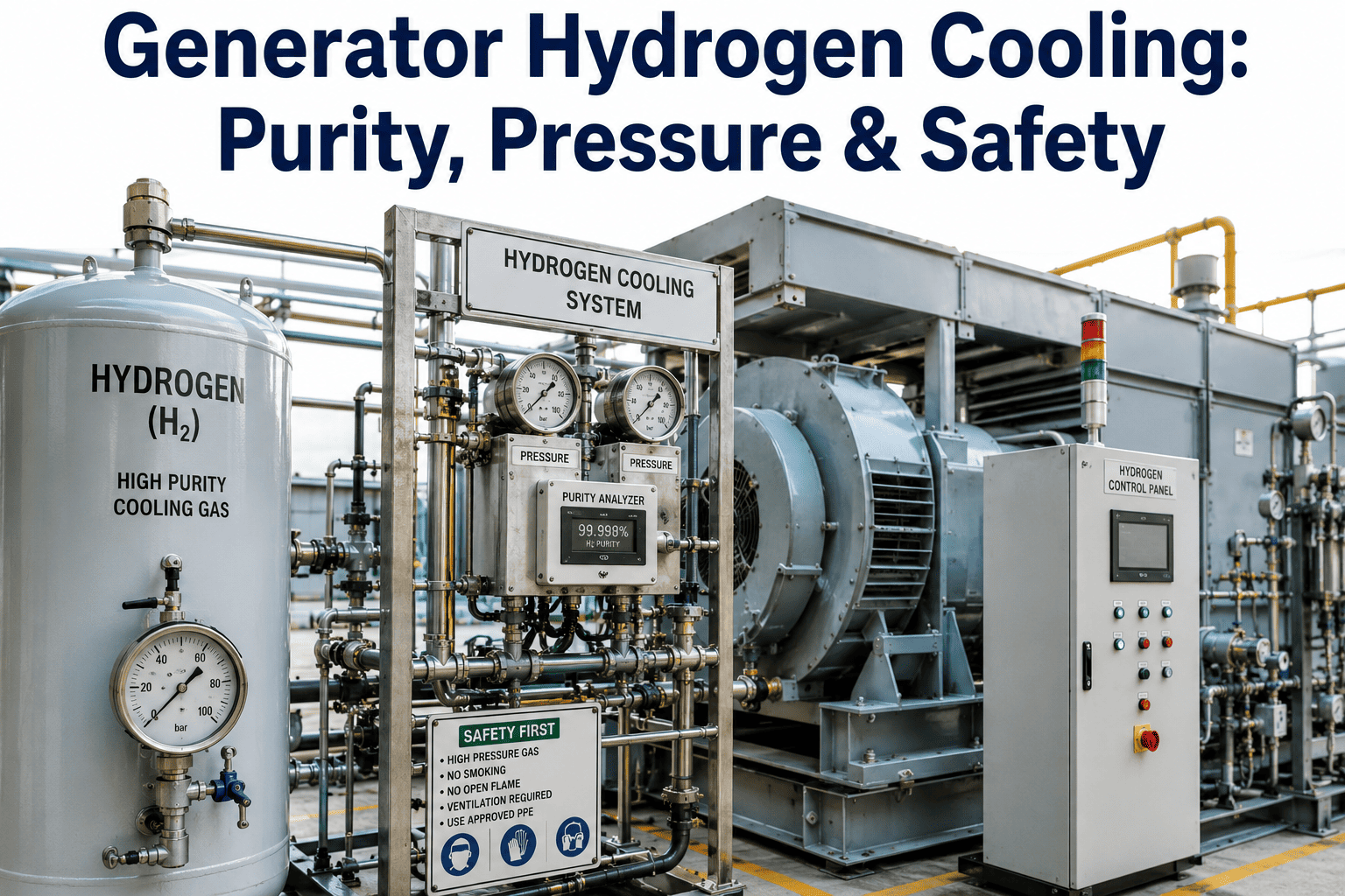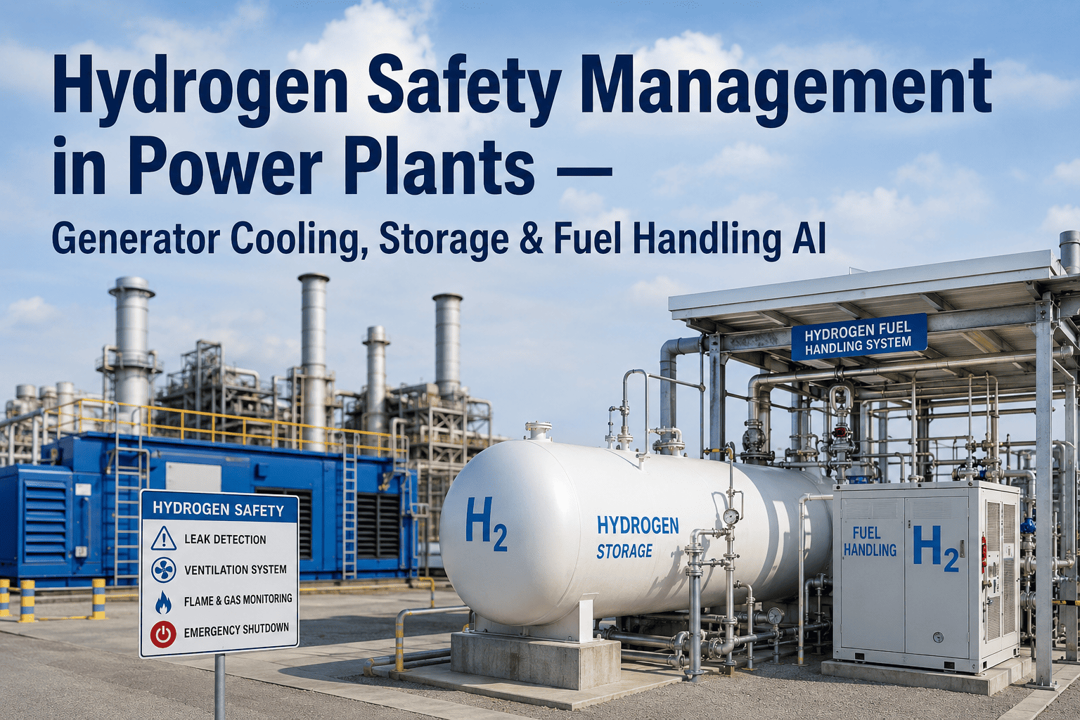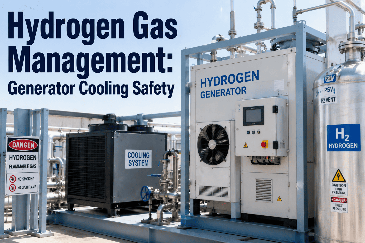
Every power plant engineer who has walked past a hydrogen-cooled generator knows the quiet unease that lives near that machine. Inside the casing spins a rotor at 3,000 or 3,600 RPM, wrapped in a gas that carries heat away seven times better than air — and would ignite in a heartbeat if it ever met the wrong mixture with oxygen. Hydrogen sits between 4% and 74% by volume in air as an explosive range, which is the widest of any common industrial gas, and it needs almost no ignition energy to go. Managing that gas — its purity, its pressure, its dew point, and the boundary between it and the atmosphere — is the single most consequential safety discipline in a hydrogen-cooled generator hall. Teams tightening their H2 management program can Book a Demo to see how iFactory unifies purity, pressure, leak, and seal-oil data into one operator picture.
Why Hydrogen Is Used to Cool Generators — and Why That Choice Creates a Safety Discipline
Hydrogen became the cooling medium of choice for large synchronous generators for reasons rooted in basic thermodynamics. Its density is roughly one-fourteenth that of air, so windage losses on a rotor spinning at 3,600 RPM drop by an order of magnitude — a huge efficiency gain on a 500 MW machine. Its thermal conductivity is about seven times higher than air and its heat capacity per unit mass is around 14 times higher, so the same volume of gas carries far more heat away from the copper windings and rotor forgings. A hydrogen-cooled generator can be built smaller for the same output, run cooler under the same load, and lose less power to internal friction than any air-cooled alternative at similar scale.
Those thermodynamic advantages come tied to an operating envelope that has to be held every second of every year. The gas has to stay pure enough to keep its cooling properties and stay out of the flammable range. It has to sit at a pressure high enough to prevent air ingress but low enough that seals and casing joints stay intact. It has to be dry enough that condensation does not form inside the casing and short-circuit windings. And it has to be contained — kept behind the seal-oil barrier and the casing, not leaking into the turbine hall where it could accumulate under a roof beam and wait for a spark. The rest of this page walks through the four operational pillars that hold that envelope, the codes that define it, and the digital monitoring approach that turns a wall of gauges into one operator picture.
The Four Safety Pillars of Hydrogen-Cooled Generator Operation
Hydrogen safety on a generator is not a single system — it is four interlocking systems that each guard against a different failure mode. Losing any one of them puts the machine at risk. Every operating utility, every OEM manual, and every insurance-driven best-practice guide reduces to the same four pillars, though the specific instruments and set points vary by machine size and vintage. Understanding them as a framework — rather than as a checklist of gauges — is what turns a compliant program into a genuinely safe one.
The Hydrogen Safety Envelope: Where Every Parameter Must Sit
A hydrogen-cooled generator does not have a single "safe" number — it has an envelope of parameters that must all sit in range simultaneously. The table below summarizes the typical operating targets found across large-frame turbine-generators, drawn from OEM manuals and IEEE guidance. Specific set points vary by machine, and the OEM manual for the specific unit is always the authoritative source, but the shape of the envelope is common across the fleet. Anything outside the green band is a signal — some are alarms, some are trends worth investigating before they become alarms, and some are conditions that require immediate load reduction or unit trip.
| Parameter | Typical Target | Alarm Threshold | Why It Matters |
|---|---|---|---|
| Casing H2 purity | > 97% for efficient operation, > 95% minimum | Below 95% investigate, below 90% load reduction | Purity below flammability margin risks explosive mixture; also degrades cooling |
| Casing pressure | Per OEM, commonly 30 – 75 psig for larger frames | Deviation of ±5% from set point | Low pressure risks air ingress; high pressure stresses seals and casing joints |
| Gas dew point | Well below minimum casing metal temperature, upper limit around 0 °C at pressure | Rising toward casing metal temperature | Condensation on windings causes insulation degradation and ground faults |
| H2 make-up rate | Steady week-over-week baseline for the machine | Sudden rise or gradual climb above baseline | Rising consumption is the earliest quantitative signal of a developing leak |
| Ambient LEL in gen hall | < 10% of LEL (0.4% H2 by volume) | 25% of LEL alarm, higher levels require evacuation | Escaped hydrogen accumulating anywhere in the hall risks ignition and explosion |
| Seal-oil differential pressure | Per OEM, oil pressure held above H2 pressure | Differential dropping toward zero or reversing | Loss of differential lets hydrogen escape through the shaft seals |
The envelope is a system, not a set of independent parameters. A drop in seal-oil differential pressure typically shows up first as elevated hydrogen make-up rate, then as declining purity, then as rising ambient LEL if the leak is large enough. Reading the envelope as a system — where a trend in one parameter predicts a movement in another — is what separates operators who catch problems days early from operators who react when the alarm sounds. This is where a unified monitoring platform earns its place: humans reading six gauges in a logbook rarely spot the pattern that a correlated trend view makes obvious.
Hydrogen Leak Detection: What Modern Practice Actually Looks Like
Leak detection on a hydrogen-cooled generator is a discipline that has evolved substantially over the past two decades. Older practice relied heavily on soap-solution surveys during outages, walkdowns with handheld thermal-conductivity leak detectors, and inference from make-up consumption trends. That practice still works — and outage-time surveys remain valuable — but modern plants layer on continuous LEL detection, optical gas imaging with CO2 tracer gas, and predictive analytics on consumption trends that flag developing leaks weeks before they become large enough to see on a handheld instrument.
The dominant leak paths on a hydrogen-cooled generator are well characterized. Shaft seals are the largest and most closely watched, because they are the deliberate rotating boundary between the pressurized H2 casing and the atmosphere. Static joints in the casing — high-voltage bushings, glands, collector terminals, end shield horizontal and vertical joints, access cover flanges, and hydrogen seal casing vertical joints — leak slowly over time as gaskets age and thermal cycling loosens fasteners. Hydrogen piping and the purity/purging cabinet contribute smaller but non-trivial contributions. Every one of these paths is a candidate for both continuous detection and periodic survey.
Low-explosive-limit detectors mounted in the generator hall, purity cabinet, seal-oil area, and at ventilation intakes provide 24/7 alarming on hydrogen accumulation. Detectors sit above likely leak points and where hydrogen — being far lighter than air — would collect, particularly under roof beams and at the ceiling of enclosed cabinets. This is the primary line of defense against a large or fast-developing leak.
Hydrogen consumption for scavenging replacement is normally steady week to week. A gradual climb above baseline consumption is often the earliest quantitative signal of a developing leak — sometimes weeks before ambient detection would trigger. Automated trending with baseline comparison catches these signals when logbook review often would not, particularly across shift handovers.
CO2 tracer gas added to the hydrogen supply at low concentration (typically under 5%) lets specialized infrared cameras visualize CO2 plumes as a proxy for hydrogen leaks. This works during full operation without a shutdown, and can pinpoint the exact leak source at a specific fitting or joint — a capability older handheld tools rarely delivered on operating machines.
During a planned unit outage, the generator can be purged of hydrogen and pressurized with CO2 or an inert gas at slightly elevated pressure. Soap-solution surveys, ultrasonic leak detectors, or OGI cameras then locate leaks at every casing joint and fitting with the generator fully accessible. This is when the highest-precision leak repair happens, and it is where the outage-cycle leak-tightness of the machine is set for the next operating period.
Codes and Standards: Where the Rules Actually Live
The regulatory landscape for hydrogen-cooled generators is layered. National codes set the fire-safety and installation minimums, industry standards define equipment specifications, and OEM manuals define the specific operating envelope for a given machine. Compliance is not optional — insurance underwriters, plant safety cases, and regulatory inspections all reference these documents. Below is the working set that a hydrogen-cooled generator operator should be familiar with, and where each one applies.
The Purity Story: Why 95% Is the Line and How Operators Hold It
The 95% purity threshold that shows up in almost every hydrogen-cooled generator procedure is not arbitrary. It sits above the flammable range with a safety margin — hydrogen is only flammable in air between roughly 4% and 74%, meaning at 95% H2 the remaining 5% is nowhere near the mixture that would burn. It also sits at a purity where the thermodynamic advantages of hydrogen cooling — low windage, high thermal conductivity — are still meaningfully present. Below 95% purity, both the safety margin and the cooling efficiency begin degrading, and most operators treat that line as the trigger for action, not the destination.
Purity is not held by installing pure hydrogen once — it drifts continuously downward during operation. The dominant reason is air release from the seal oil. Seal oil is exposed to atmospheric air on one side of the shaft seal and to pure hydrogen on the other. Air dissolves into the oil at the atmospheric side, travels through the oil circulation, and releases into the hydrogen atmosphere on the casing side. This slow, continuous air ingress is why every hydrogen-cooled generator has a scavenging system — a small continuous vent that discards a portion of the casing gas and replaces it with pure hydrogen make-up. The scavenge rate, hydrogen make-up rate, and casing purity form a three-way relationship that operators tune to hold purity in target with minimum hydrogen consumption.
When purity trends downward faster than the seal-oil aeration baseline explains, the investigation shifts from routine scavenge tuning to leak hunting. When purity trends downward with elevated seal-oil flow, the investigation shifts toward the shaft seals themselves. When purity trends downward with normal seal-oil flow but rising make-up consumption, the leak is more likely in the static casing joints or hydrogen piping. Reading the correlated signals is what tells operators where to look, and a unified monitoring platform that shows all three parameters on one trend view is what makes that reading possible in real time.
A Scenario Walkthrough: The Overnight Purity Drop
Consider a 400 MW hydrogen-cooled generator running at rated load. On the day shift the purity analyzer reads 97.8%, casing pressure is at the OEM set point, seal-oil differential is normal, LEL detectors in the hall are all zero, and hydrogen make-up consumption is at the machine's usual baseline. The plant runs normally through the evening. At 03:00 the control room operator notices that purity has drifted to 96.4% over the past six hours, still comfortably in range but a larger drop than usual for the machine.
In a plant with fragmented instrumentation, this trend often gets logged and left for day shift to investigate. In a plant with unified monitoring, the operator opens a correlated trend view and sees three parameters moving together — purity down 1.4 points, seal-oil flow on the exciter-end seal up 8%, and hydrogen make-up rate up about 12% over the same window. Casing pressure is stable and LEL detectors are still zero. The pattern is a classic slow shaft-seal degradation on the exciter-end seal, showing up first in oil flow and consumption, then in purity, well before it would trigger any ambient alarm. The night shift operator dispatches a walkdown of the exciter-end seal area, day shift confirms the pattern, and the machine is scheduled for seal inspection at the next planned outage window rather than proceeding toward a forced outage when the seal fails harder.
This is the practical difference a unified monitoring approach delivers. The individual instruments existed in the plant already — every hydrogen-cooled generator has purity, pressure, seal-oil flow, and make-up meters. What the platform adds is the correlated view that turns three independent indications into one diagnosis, plus the trending memory that separates a slow developing pattern from routine variation. That difference is worth days or weeks of early warning on developing seal issues, and often the difference between planned repair and forced outage.
Emergency Response: What Every H2 Generator Operator Should Have Rehearsed
The four safety pillars are designed to keep the generator inside its envelope, but no envelope is guaranteed. Real emergency response depends on rehearsed procedures for the abnormal conditions the pillars are designed to prevent. Below are the four scenarios that every hydrogen-cooled generator operating crew should have walked through, and the response principles that reduce them from potential catastrophes to controlled events.