Blast furnaces and basic oxygen furnaces operate at the extreme edge of industrial thermal tolerance — shell temperatures exceeding 400°F at the tuyere band, tap hole areas hot enough to liquefy steel-grade refractory, BOF vessel interiors above 3,000°F during oxygen blowing cycles. These conditions make human inspection dangerous, intermittent, and incomplete. Yet the equipment reliability demands on those same assets have never been higher, with blast furnace campaign targets routinely exceeding 20 million tons of hot metal and BOF vessel campaigns pushing past 5,000 heats between relines. The gap between what needs to be inspected and what can be inspected by human crews under those thermal conditions is the gap that robotic inspection systems — from thermal-imaging quadrupeds to rail-mounted refractory scanners — are closing at integrated steel mills across the United States. iFactory's Robotics AI and Predictive Maintenance modules provide the data infrastructure to manage robotic inspection workflows, aggregate sensor data across furnace zones, and generate actionable insights that extend campaign life, reduce safety incidents, and eliminate the inspection blind spots that have been accepted as unavoidable for decades. Book a Demo to see iFactory's robotic inspection management platform configured for a blast furnace or BOF shop environment.
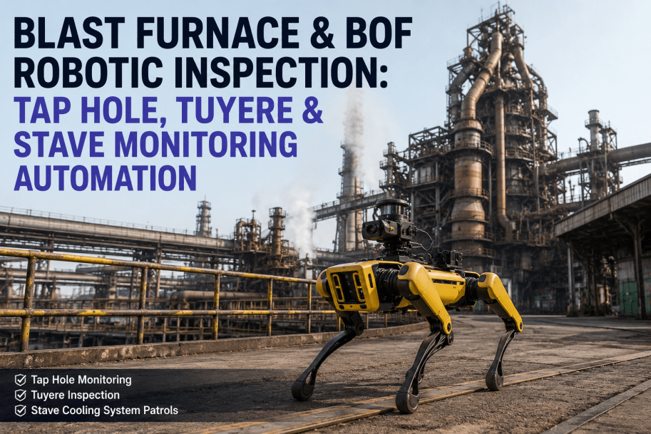
Blast Furnace and BOF Robotic Inspection — From Tap Hole Monitoring to Stave Cooling Patrol Automation
Robotic inspection systems purpose-built for blast furnace and BOF environments are delivering measurable improvements in refractory life, safety incident reduction, and unplanned outage prevention at steel plants deploying them in production. iFactory's platform connects robotic inspection data to maintenance workflows, trend analysis, and compliance documentation — without disrupting existing furnace control systems.
Why Blast Furnace and BOF Inspection Has a Robotics-Sized Gap — and What It Costs Every Day It Remains Unaddressed
The thermal and physical conditions inside and around a blast furnace and BOF create inspection environments that no human should occupy for extended periods. Tap hole areas radiate enough heat to limit manual thermal camera surveys to 30-second bursts from 15 feet away. Tuyere bands operate at surface temperatures that preclude close approach without cooling suits. Stave cooler shell plates are distributed across hundreds of square feet of furnace elevation that no single inspector can cover comprehensively in a shift. And BOF vessel interiors after tapping require cooling periods of 60–90 minutes before a human can enter for inspection — time that directly reduces vessel availability. The cost of these inspection gaps is measured in preventable failures.
Undetected Tap Hole Refractory Degradation
Tap hole refractory erosion accelerates unpredictably as the campaign progresses, yet most mills inspect tap hole condition visually once per shift. Refractory thinning that progresses between inspections can lead to sudden breakout events — tap hole breakthroughs that force emergency furnace shutdowns lasting 24 to 72 hours and costing $500,000 to $2,000,000 in lost production and refractory repair.
Undiscovered Tuyere Coolant Leaks
Tuyere coolant leaks — water entering the furnace through cracked or eroded tuyere bodies — are among the most dangerous events in blast furnace operations, creating hydrogen explosion risk that has caused fatalities at steel plants globally. Manual tuyere inspection schedules of once per week mean a leak can develop, worsen, and persist for days before detection. Each tuyere that fails undetected carries a replacement cost of $15,000–$40,000 plus production impact.
Incomplete Stave Cooling System Coverage
A typical blast furnace has 40 to 80 stave coolers distributed across multiple cooling levels, each with a heat flux that varies with campaign age, burden distribution, and operating conditions. Manual thermal patrols using handheld IR cameras cover 30–40% of the stave surface per shift at most mills. Stave cooler failures that begin as localized hot spots can progress to shell plate damage within days when the early thermal signature is missed — a stave replacement event costs $200,000–$800,000 and requires a furnace outage of 3 to 7 days.
Invisible BOF Refractory Erosion Between Laser Surveys
BOF vessel refractory lining erosion is measured by laser profiling every 50 to 100 heats — meaning 98% of the campaign length between measurements is a blind period. Refractory wear that accelerates due to localized slag attack or oxygen lance impingement can penetrate the working lining and expose the safety lining between scheduled surveys, forcing an unscheduled vessel repair that costs $300,000–$1,200,000 and disrupts the entire steelmaking schedule.
Paper-Based Inspection Data That Prevents Trend Analysis
At most integrated mills, furnace inspection data is recorded on paper checklists or entered into spreadsheets — making year-over-year trend analysis, campaign-to-campaign comparison, and predictive maintenance model training impossible. A data infrastructure gap that prevents the plant from learning from its own inspection history is the root cause of the other four inspection gaps. Book a Demo to see iFactory's digital inspection management workflow for blast furnace and BOF assets.
Continuous Tap Hole Thermal Monitoring — The End of Between-Inspection Blind Spots
The tap hole is the most thermally stressed single component on a blast furnace. Each cast pushes 5 to 10 tons of hot metal per minute through the tap hole channel at 2,500°F, progressively eroding the refractory clay gun mix and the surrounding taphole block. Robotic tap hole monitoring replaces the once-per-shift handheld thermal scan with continuous, automated thermal imaging that tracks tap hole condition throughout every cast — identifying developing hot spots, refractory thinning trends, and channel enlargement before they reach critical levels.
Mid-Wave Infrared Camera Integration
Robotic platforms equipped with MWIR cameras (3–5 micron spectral range) maintain continuous optical coverage of the tap hole area from a fixed or pan-tilt mount positioned 15–25 feet from the taphole. The camera captures thermal data during every phase of the cast cycle — drilling, idle flow, and clay gunning — building a time-series thermal model that detects temperature excursions as small as 15°F within seconds of onset.
Predictive Tap Hole Life Estimation
AI models trained on tap hole geometry history, thermal profile data, and cast frequency predict remaining tap hole refractory life with ±5% accuracy at a 72-hour horizon — enabling scheduled gunning and clay gun maintenance before damage occurs. The model ingests thermal data from every cast cycle and updates the remaining life estimate continuously, triggering a preventive work order in iFactory's CMMS module when predicted remaining life falls below the operator-defined threshold.
Emergency Notification and Work Order Generation
When thermal monitoring detects a developing anomaly that exceeds severity thresholds — such as a localized hot spot with a temperature rise rate above 50°F per hour — the system generates an immediate alert to furnace operators through iFactory's real-time monitoring dashboard and creates a preventive maintenance work order for the refractory team, capturing the thermal data, time series, and camera imagery for root cause analysis.
Robotic Tuyere Leak Detection and Condition Assessment — Every Tuyere, Every Shift
Tuyere inspection at most blast furnaces is a weekly visual check performed by a furnace inspector who opens the tuyere observation door and looks for visible coolant leaks, flame pattern anomalies, or tuyere body discoloration. The inspection covers 30 to 40 tuyeres per furnace, takes 2 to 3 hours when the furnace is in stable operation, and relies on the inspector's personal judgment of what constitutes a normal tuyere appearance. Robotic tuyere inspection systems replace this manual process with automated, instrumented inspection of every tuyere every shift — detecting coolant leaks, tuyere body erosion, and flame pattern changes at a sensitivity level that human visual inspection cannot match.
| Inspection Dimension | Manual Tuyere Inspection | Robotic Tuyere Inspection | Improvement |
|---|---|---|---|
| Inspection frequency | Weekly — 6 tuyeres visually checked per shift | Every tuyere, every shift, fully automated | 7x frequency increase |
| Coolant leak detection latency | 1–7 days from leak onset | Real-time — flow + thermal anomaly within minutes | Eliminates multi-day latency |
| Hydrogen explosion risk window | Open — inspector opens tuyere door to look inside | Closed — robot inspects via optical port without opening | Risk eliminated during inspection |
| Data capture format | Paper log or spreadsheet entry | Digital record with thermal image, flow data, AI trend analysis | Searchable, analyzable history |
| Detection sensitivity | Visible coolant spray or tuyere body discoloration only | Coolant flow deviation >2%, thermal gradient anomaly, IR signature change | Sub-visual leak detection |
Automated Stave Cooling System Robotic Patrols — From Localized Scanning to Full Furnace Coverage
Stave cooling system integrity is the single most important determinant of blast furnace shell life. A stave cooler that fails and goes undetected allows furnace heat to transfer to the shell plate — causing localized overheating, plate distortion, and in extreme cases, shell breakthrough. Robotic patrol systems designed for stave cooling inspection replace the manual thermal walk-down with systematic, instrumented coverage of the entire stave surface area on a defined frequency, ensuring that no stave cooler operates outside its design thermal envelope for more than a single patrol cycle.
Phase 1 — Programmed Patrol Route Execution
A quadruped or rail-mounted robot executes a pre-programmed patrol route that covers all stave cooling levels — typically 4 to 8 levels on a blast furnace stack, each with 8 to 12 stave coolers. The robot follows a fixed path that ensures consistent thermal data collection at the same locations during every patrol cycle, enabling direct comparison of thermal signatures across patrols.
Phase 2 — Multi-Spectral Thermal Scanning
MWIR and LWIR cameras on the robotic platform capture a full thermal map of each stave cooler's working surface and the adjacent shell plate area. The robot maintains a consistent standoff distance of 6 to 10 feet from the stave surface, with a thermal resolution of 640 x 512 pixels and temperature measurement accuracy of ±2°F across a measurement range of 100°F to 500°F.
Phase 3 — AI Anomaly Detection and Trend Analysis
iFactory's AI platform compares each stave cooler's thermal signature against its own historical baseline and against the population of adjacent stave coolers at the same furnace elevation. Any stave cooler showing a surface temperature deviation greater than 15°F from its baseline, or a temperature gradient that exceeds 25°F across its cooling channel pattern, is flagged for review. The AI model tracks temperature trends across patrol cycles to distinguish between stable operating variations and developing failure modes.
Phase 4 — Automated Work Order Generation and Escalation
When stave cooler anomalies are detected, iFactory automatically creates a maintenance work order that includes the thermal imagery, temperature trend data, stave cooler identification, and recommended inspection or repair action. Anomalies with temperature rise rates above 30°F per patrol cycle are escalated to the furnace operations manager through the iFactory alert system, with the full thermal data package attached for immediate decision-making.
Robotic BOF Refractory Lining Inspection — Eliminating the 98% Blind Window Between Laser Surveys
Basic oxygen furnace vessel refractory inspection has been limited by the same constraint for decades: the vessel must be cooled, the slag must be removed, and a human inspector or laser profiling system must enter the vessel to measure lining thickness. This process takes 60 to 90 minutes per inspection and is typically performed every 50 to 100 heats — leaving the vessel unmonitored for 98% of its campaign. Robotic inspection systems purpose-built for BOF vessels close this gap by deploying tethered crawlers or articulated arms that can inspect the vessel lining without requiring full cool-down or human entry, performing partial lining assessments between heats and full lining surveys during scheduled maintenance windows.
Rapid Partial Lining Assessment During Tapping
A tethered crawler robot deployed through the BOF cone can perform a partial inspection of the upper cone and barrel sections while the vessel is in tapping position — capturing thermal images and surface profile data of the 30–40% of the lining that is accessible during the tap. This between-heat inspection provides a daily lining condition snapshot that identifies developing wear patterns before the next full laser survey.
Automated Laser Profiling During Maintenance Windows
An articulated robotic arm equipped with a 3D laser profiler can map the full BOF vessel lining — including the trunnion, barrel, cone, and tap hole areas — in 12 to 15 minutes, compared to 45 to 60 minutes for manual laser profiling. The robotic arm enters the vessel through the cone opening and executes a programmed scan pattern that captures lining thickness at a grid resolution of 2 inches, generating a 3D point cloud that is compared against the previous scan to calculate wear rates.
Predictive Refractory Life Modeling
iFactory's AI platform ingests laser profiling data from each vessel inspection, combined with heat-by-heat production data (blow time, oxygen volume, lance position, slag chemistry, tapping temperature), to build a refractory wear model that predicts remaining lining life for each vessel zone. The model identifies zones where wear is accelerating and recommends targeted gunning repairs before the safety lining is exposed — extending vessel campaign life by 8–15% at plants that have implemented the system. Book a Demo to see iFactory's refractory life prediction dashboard configured for a BOF vessel.
Choosing the Right Robotic Platform for Each Blast Furnace and BOF Inspection Application
No single robotic platform covers all blast furnace and BOF inspection requirements. The thermal environment, physical access constraints, payload requirements, and inspection frequency for each application area determine which platform type is most cost-effective. The table below compares the four robotic platform categories currently deployed at integrated steel mills for furnace inspection, with their operating specifications and best-fit applications.
| Robot Platform | Best Fit Application | Temperature Tolerance | Payload Capacity | Deployment Type |
|---|---|---|---|---|
| Quadruped (e.g., Spot) | Stave cooling patrol, tuyere band scanning, casthouse floor inspection | Up to 250°F ambient (with thermal shield) | 15 lb | Mobile — patrol route programmed, recharged at docking station |
| Tracked crawler | Tap hole area inspection, casthouse runner thermal monitoring, BOF cone entry | Up to 400°F ambient (water-cooled chassis) | 50 lb | Tethered — power and data through cable, unlimited runtime |
| Rail-mounted gantry | BOF vessel lining profiling, continuous furnace stack thermal monitoring | Up to 350°F ambient | 30 lb | Fixed rail — continuous via power rail, consistent patrol path |
| Fixed articulated arm | Tuyere precision inspection, tap hole clay gun nozzle inspection, sensor positioning | Up to 200°F ambient (enclosed base station) | 100 lb | Fixed installation — dedicated to one inspection station |
What Integrated Steel Plant Operations Professionals Say About Robotic Furnace Inspection
I have managed blast furnace operations at integrated mills for 28 years and have watched the industry approach furnace inspection the same way my entire career — send an operator with a handheld IR camera and a clipboard once per shift, write down the readings, and hope nothing changes between shifts. The assumption has always been that the furnace will tell you when something is wrong, and it does — but only if you are looking at the right data at the right cadence. Robotic inspection changes the fundamental detection equation. At a mill where we deployed a quadruped for stave cooling patrol on a 32-hundred-cubic-meter blast furnace, the robot identified a stave cooling channel blockage on level 3 within 48 hours of deployment — a blockage that had been producing a localized hot spot for at least three weeks based on the thermal trend data the robot captured on its first patrol cycle. The hot spot was 160°F above the adjacent stave temperature, well outside the design envelope, and visible in the thermal imagery. That stave had been inspected manually twice per shift for three weeks. No one saw it. The robot saw it on the first pass. That is the difference between an inspection system that covers 30% of the surface on a good shift and one that covers 100% of the surface on every patrol.
— Former Blast Furnace Operations Manager, Integrated Steel Mill — 28 Years Steel Industry Operations — Licensed Professional Engineer (PE), Metallurgical Engineering — AIST Steel Technology Association MemberDeploying Robotic Inspection at a Blast Furnace and BOF Shop — A Phased Approach Delivering ROI in 90 Days
Phase 1: Weeks 1–4
Site assessment and robotic platform selection. Thermal imaging sensor specification. Installation of robotic charging stations and network infrastructure. First stave cooling patrol routes programmed and tested.
Phase 2: Weeks 5–8
Tap hole thermal monitoring robot deployment. Tuyere inspection automation integration. AI model training on initial thermal data sets. First automated inspection reports delivered to operations team.
Phase 3: Weeks 9–14
BOF vessel crawler robot deployment. Refractory laser profiling integration with iFactory AI platform. Full furnace zone coverage operational. Predictive wear models calibrated on first 30 days of combined data.
Phase 4: Weeks 14–18
iFactory platform fully integrated with robotic inspection workflow. Automated work order generation from inspection data active. Compliance documentation and trend reporting configured. Operations team training completed.
Continuous Optimization
AI models retrain on accumulating inspection data. Patrol routes optimized based on historical anomaly distribution. Predictive wear models updated with each campaign phase. Quarterly ROI review and platform expansion planning.
Your Blast Furnace and BOF Inspection Data Already Contains the Failure Signatures You Are Trying to Prevent
Every tap hole thermal gradient, every tuyere coolant flow deviation, every stave cooler temperature trend is a signal that robotic inspection and AI analysis can turn into a preventive action — before the breakout, before the leak, before the unscheduled outage. See iFactory's robotic inspection management platform running on a furnace today and build the ROI case for your mill.
Frequently Asked Questions About Blast Furnace and BOF Robotic Inspection
Robotic platforms deployed in blast furnace tap hole zones use water-cooled chassis enclosures, thermal shielding, and standoff positioning at 15–25 feet from the tap hole to protect electronics and sensors. MWIR thermal cameras operate behind sapphire or germanium windows that transmit IR wavelengths while blocking conducted heat. The iFactory platform does not require the robot to contact the tap hole — all measurements are non-contact thermal and optical readings from a protected position.
Yes. iFactory connects to existing blast furnace and BOF instrumentation via OPC-UA, Modbus, and API protocols — ingesting data from furnace control systems, stave cooling historians, tuyere coolant flow meters, and BOF lance position sensors. Robotic inspection data is merged with existing instrumentation data in the iFactory analytics platform to create a unified furnace health dashboard that correlates robotic thermal readings with plant sensor data for more accurate anomaly detection.
Typical payback at an integrated steel mill with one blast furnace and two BOF vessels is 6 to 11 months. ROI is driven by tap hole breakout prevention ($500K–$2M per event avoided), stave cooler failure early detection ($200K–$800K per replacement avoided), tuyere leak prevention ($15K–$40K per tuyere plus safety risk elimination), and BOF vessel campaign extension (8–15% longer campaign life, worth $1M–$4M per campaign at most integrated mills).
Robotic tuyere inspection systems use optical inspection ports installed on the tuyere observation doors — small sapphire windows that allow the robot's thermal camera and visual camera to inspect the tuyere body and flame pattern without opening the door. The robot positions its sensor package at each tuyere port sequentially, capturing thermal and visual data in 30–45 seconds per tuyere. The full tuyere band inspection for a 40-tuyere furnace takes approximately 25 minutes and does not require any furnace operating parameter changes.
Yes. BOF vessel crawler robots and rail-mounted gantry systems are designed to operate in coordination with vessel movement. The tethered crawler robot is deployed through a fixed entry port in the BOF cone and inspects the vessel lining while the vessel is in the upright or tapping position. The rail-mounted laser profiling system inspects the vessel during scheduled maintenance windows when the vessel is tilted to the charging position. The iFactory platform tracks vessel position status and prevents inspection deployment during vessel movement for safety interlock compliance. Book a Demo to see the full robotic inspection workflow configured for your furnace and BOF shop.
Robotic Inspection Closes the Gap Between What Needs to Be Monitored and What Can Be Monitored
The blast furnace and BOF inspection problem has never been a technology problem. Thermal cameras, coolant flow sensors, and laser profilers have existed for decades. The problem has always been a deployment and data integration problem — getting those sensors to the inspection point at the right frequency, collecting the data in a consistent format, and connecting the inspection findings to maintenance actions before the failure occurs.
Robotic inspection platforms solve the deployment problem by bringing the sensors to every inspection point on every patrol cycle. iFactory's platform solves the data integration problem by connecting robotic inspection data to the CMMS, the historian, the predictive maintenance model, and the compliance reporting workflow — creating a closed loop from sensor reading to maintenance action that eliminates the manual steps that have made furnace inspection reactive rather than predictive. The 40–65% reduction in human heat-zone exposure, the 8–15% extension in campaign life, and the 6–11 month payback are not theoretical targets — they are the operational outcomes that integrated steel mills achieve when they deploy robotic inspection with the right data infrastructure. Book a Demo to see how iFactory's Robotics AI and Predictive Maintenance modules connect your robotic inspection data to maintenance workflows and campaign life optimization.
Your Furnace Is Sending Signals Every Second — Robotic Inspection Plus iFactory AI Turns Those Signals into Campaign-Extending Decisions
Every tap hole thermal signature, every stave cooler temperature trend, every tuyere coolant flow deviation is data that iFactory can aggregate, analyze, and act on — before the failure event. See iFactory running with robotic inspection data from a blast furnace or BOF shop and calculate the campaign life impact for your mill.