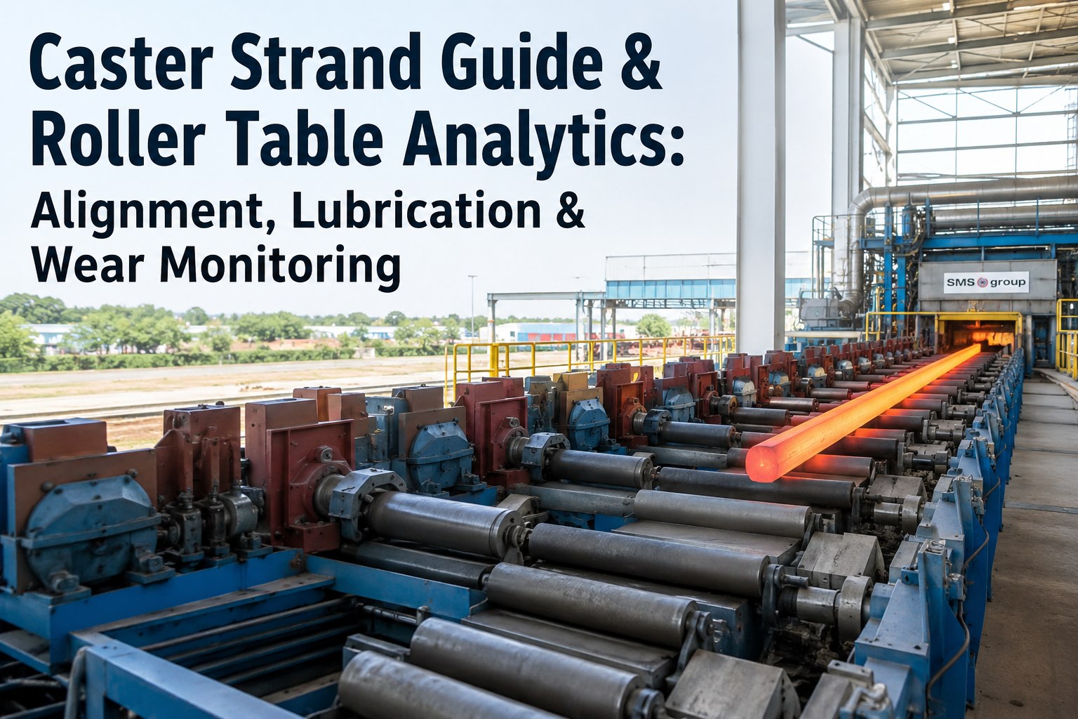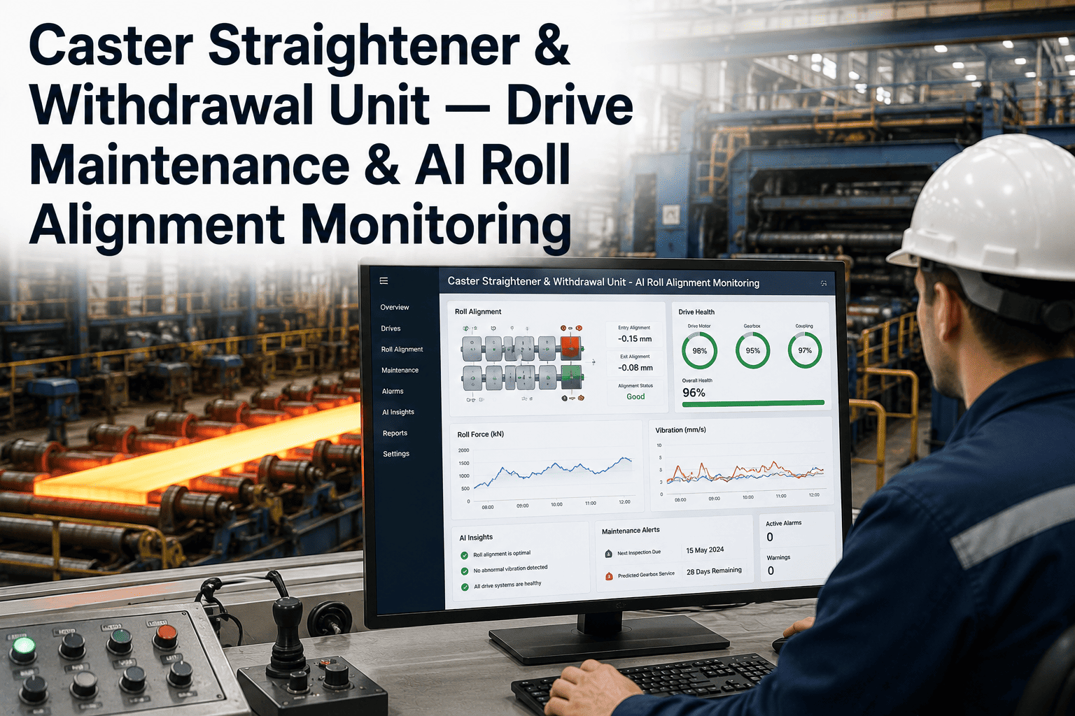
The withdrawal and straightening unit is the point in continuous casting where a still-molten steel core meets its final geometry, and where a worn pinion gear or a half-degree of roll misalignment can turn a routine sequence into a multi-million-dollar breakout. Every driven roll pair in this stand works against the same clock as the strand shell solidifying inside it, which means drive slip, uneven torque sharing across motors, or a straightener roll sitting fractions of a millimeter out of line will not stay hidden for long. Maintenance managers who treat the straightener and withdrawal drive as a single monitored system, rather than a set of unrelated motors and gearboxes, catch these problems while they are still adjustments rather than failures. Plants that book a demo of iFactory's AI monitoring for this stand typically start with the drive train first, since it is where the earliest and clearest wear signatures appear.
Catch Straightener Drive Wear Before It Becomes a Breakout
iFactory tracks drive motor condition, pinion gear wear, and roll alignment accuracy across every withdrawal and straightener stand in real time, so torque imbalance and misalignment surface as work orders instead of surface cracks.
Why the Withdrawal and Straightener Stand Sets the Ceiling on Strand Quality
A withdrawal and straightening unit typically runs four to eight driven roll pairs, each carrying its own gearbox, motor, and universal joint, all of which must share drawing force within tight tolerance while the strand is unbent across a multi-point straightening span. Speed control across that drive group needs to hold within a fraction of a percent at typical casting speeds, because any variation ripples straight back to mold level control and shell thickness uniformity. When one motor drifts toward overload while another idles, the casting force applied across the slab face becomes uneven, and that unevenness shows up later as surface quality complaints from customers who never see the caster floor. Reliability teams that instrument this drive group as one coordinated system, instead of monitoring individual motors in isolation, are the ones who catch load-sharing drift while it is still a calibration issue.
Pinion Gear Wear: The Failure Mode That Hides Until It Doesn't
Pinion gears in a withdrawal drive absorb reversing loads, thermal cycling from strand proximity, and contamination from scale and cooling water spray, all of which accelerate tooth wear in ways that are difficult to catch on a fixed maintenance calendar. Because gear wear develops gradually and the drive keeps running within an apparently normal speed band, plants relying on scheduled inspection alone often only discover advanced wear when backlash starts to affect roll positioning accuracy. AI condition monitoring compares vibration signatures, motor current harmonics, and gearbox oil particle counts against learned baselines for each specific gear pair, flagging the early gear mesh frequency shifts that precede visible tooth damage by weeks. Engineers who book a consultation with iFactory can review real gear wear signatures from comparable caster installations before selecting sensor placement for their own stand.
| Wear Stage | Vibration Signature | Motor Current Signal | Consequence If Missed |
|---|---|---|---|
| Early Mesh Wear | Gear mesh frequency sideband growth | Minor harmonic distortion | None yet, monitoring window open |
| Moderate Tooth Wear | Rising 2x and 3x mesh harmonics | Periodic torque ripple | Backlash affecting roll timing |
| Advanced Pitting | Broadband high-frequency noise | Repeating current spikes | Roll positioning drift, alignment loss |
| Tooth Fracture Risk | Impact transients, sideband spread | Sudden torque loss events | Drive slip, strand stall risk |
Roll Alignment Accuracy: Why Fractions of a Millimeter Matter
Multi-point straightening depends on each roll sitting at the exact elevation and angle the unbending curve requires, since the strand shell is unbent gradually across several rolls rather than all at once. A roll that has drifted out of position, whether from bearing wear, thermal distortion of the frame, or gradual settling under repeated casting force, changes the strain rate applied to the still-solidifying shell at that point in the curve. If that strain rate exceeds the tolerance the steel grade can absorb at that temperature, the result is straightening cracks, a transverse surface defect that shows up only after rolling and often traces back to a stand the operator never suspected. AI-driven alignment monitoring uses continuous roll position and load data to detect this drift long before it reaches a defect-causing threshold, converting an invisible mechanical trend into a scheduled bearing or shim adjustment.
Roll Elevation Drift
Continuous position tracking on each roll pair detects gradual elevation change from bearing wear or frame settling, comparing live position against the commissioned straightening curve rather than a static tolerance band.
Load Distribution Skew
When one roll begins carrying disproportionate load relative to its neighbors, that imbalance is an early signal of misalignment even before position sensors register measurable drift, and it is visible in torque data first.
Bearing Housing Vibration
Bearing wear inside the roll housing changes vibration signatures well before it affects roll position directly, giving maintenance teams a lead indicator that a given roll pair needs inspection at the next window.
Thermal Frame Distortion
Uneven thermal expansion of the stand frame across a casting sequence can shift multiple rolls simultaneously, a pattern that AI baselining separates from single-roll mechanical wear so root cause is identified correctly.
See Your Straightener Drive Data the Way Our Platform Sees It
iFactory's engineering team will walk through motor, gearbox, and roll alignment monitoring for your specific caster configuration, using data patterns from installations running similar drive architectures.
Load Sharing Across Drive Motors: The Overlooked Reliability Metric
Modern withdrawal drives use AC variable frequency motors with a shared speed setpoint, but manufacturing tolerances, coupling wear, and gear condition mean each motor's actual output torque drifts differently over time even when all are commanded identically. Left uncorrected, some motors run consistently near full load while others contribute little, a pattern that causes repeated overcurrent trips, wastes energy in the underloaded units, and applies uneven casting force across the slab that shows up later as a quality complaint rather than a maintenance ticket. AI-based load distribution monitoring calculates each motor's actual contribution continuously and flags divergence long before it reaches a trip threshold, giving maintenance managers a data-backed case for gearbox or coupling inspection instead of a reactive call after a fault.
Bringing AI Drive Monitoring Onto an Existing Caster
Adding condition monitoring to a straightener and withdrawal drive does not require replacing the drive system, but it does require a structured rollout so sensor data becomes trustworthy before it drives maintenance decisions. Most maintenance teams find it more effective to instrument one strand fully before expanding across a multi-strand caster, since baseline behavior varies enough between stands that lessons learned on the first installation shorten every subsequent one.
Instrument the Drive Group
Vibration, current, and thermal sensors are added to each motor, gearbox, and roll bearing housing in the withdrawal and straightener stand, with data routed into the platform on a common time base.
Establish Baselines
The platform learns normal vibration, torque, and alignment behavior across several casting sequences, accounting for grade changes and speed variation before flagging deviations as significant.
Validate Against Known Events
Historical maintenance records and any past straightening-crack incidents are cross-checked against the sensor baseline to confirm the model would have flagged the same conditions earlier.
Move Into Live Alerting
Once validated, the platform shifts from passive baselining to active alerting, feeding pinion wear, alignment drift, and load-sharing anomalies directly into the maintenance work order queue.
Caster Straightener and Withdrawal Drive Monitoring — Frequently Asked Questions
How early can AI monitoring detect pinion gear wear compared to scheduled inspection?
AI monitoring tracks gear mesh frequency and current harmonic shifts continuously, which typically surface weeks before wear would be caught on a fixed inspection interval. This gap matters most on stands running high sequence counts, where the interval between planned inspections can span several weeks of continuous operation. Teams that book a demo can see actual detection lead-time data from comparable installations.
Does roll alignment monitoring require stopping the caster to install sensors?
Most position and vibration sensors can be installed during a scheduled maintenance window without extending planned downtime, since mounting points on bearing housings and roll frames are typically accessible without disassembling the drive train. Full sensor commissioning and baseline validation happen while the caster continues normal production.
What causes uneven load sharing across withdrawal drive motors?
Uneven load sharing usually stems from small differences in gear condition, coupling wear, or calibration drift between motors that are all commanded to the same speed setpoint but not the same actual torque output. Over time these differences compound, leaving some motors chronically overloaded while others contribute minimal drawing force to the strand.
Can this monitoring approach help identify the root cause of straightening cracks?
Yes, straightening cracks are frequently traced back to a specific roll operating outside its intended alignment curve, and continuous position and load data makes it possible to correlate a defect batch with the exact stand and timeframe responsible. This turns a metallurgical investigation that once took weeks into a data query that takes minutes.
How does drive monitoring integrate with an existing CMMS or maintenance workflow?
iFactory's platform pushes flagged anomalies directly into the existing work order system as prioritized maintenance tasks rather than requiring maintenance teams to monitor a separate dashboard. Reliability engineers who contact support can review integration options for their specific CMMS before rollout begins.
Stop Straightening Cracks and Breakouts Before They Start
iFactory's AI platform gives caster maintenance teams continuous visibility into drive motor condition, pinion gear wear, and roll alignment accuracy, turning gradual mechanical drift into scheduled maintenance instead of unplanned strand loss.