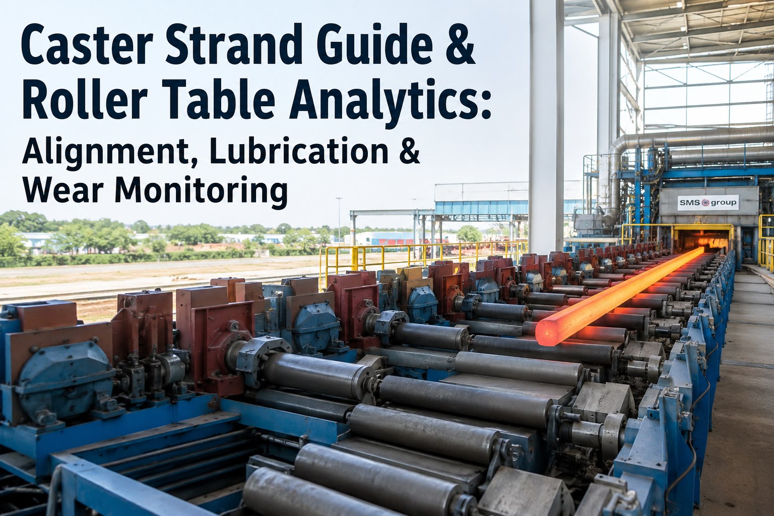
In continuous casting operations, the strand guide system is the mechanical backbone that determines slab shape, surface quality, and internal soundness from the moment liquid steel leaves the mold to the point of complete solidification. A misaligned roller, an under-lubricated bearing, or an undetected wear pattern in the withdrawal unit does not just create a maintenance problem — it creates a quality crisis that shows up three operations later as a rolled product rejection. Caster strand guide and roller table analytics transforms this high-consequence, low-visibility subsystem into a monitored, trended, and predictable operation. This guide covers alignment measurement, lubrication scheduling, bearing condition monitoring and automated wear tracking for U.S. continuous casting operations running billet and bloom, and slab casters. Book a Caster Analytics Review.
Why Strand Guide Analytics Is the Most Underfunded Line in the Caster Budget
The continuous caster strand guide system contains hundreds of individual rollers arranged in segments from the mold exit to the torch cutoff. Each roller is a precision component operating under extreme thermal load, ferrostatic pressure from the liquid core, and mechanical stress from the withdrawal force. Despite this, most U.S. caster operations still rely on scheduled segment pulls based on tonnage intervals — a calendar-based approach that misses gradual misalignment, progressive bearing degradation, and lubrication starvation that begin well before the scheduled pull.
Industry data from AIST continuous casting conferences consistently shows that undetected strand guide failures — roll surface cracking, segment misalignment beyond 0.5 mm, and bearing seizure — are responsible for 25–35% of internal quality defects (centerline segregation, rhomboidity, off-corner cracks) in slabs that pass visual surface inspection. These are defects that are invisible at the caster but become rejections at the hot mill or at the customer. Analytics closes this detection gap by providing continuous, trended data on the parameters that predict these failures before they become embedded in the product.
Roll Alignment Measurement: From Manual Survey to Continuous Monitoring
Roll alignment in the strand guide system is measured across three dimensions: roll gap (distance between opposed rolls), roll parallelism (angular deviation from the centerline axis), and segment-to-segment offset (vertical and horizontal position relative to the theoretical strand path). Traditional alignment is verified during segment rebuilds using mechanical gauges and string-line methods — a process that captures alignment at a single point in time and under ambient temperature conditions, not under operating thermal load.
Roll Gap Measurement & Tolerances
Roll gap is the primary dimensional parameter controlling slab thickness uniformity. For a slab caster producing 220 mm thickness, nominal roll gap equals product thickness plus thermal expansion allowance. The table below defines the critical thresholds used by leading U.S. slab casters.
| Parameter | Nominal | Warning | Action Required | Measurement Method |
|---|---|---|---|---|
| Roll Gap Deviation | ± 0.3 mm of design | ± 0.5 mm | > ± 0.8 mm | Laser gap sensor / wedge gauge |
| Gap Taper (per segment) | Per design taper | ± 0.2 mm/m | > ± 0.4 mm/m | CMM at segment rebuild |
| Thermal Expansion Offset | Design + 0.1–0.4 mm | Outside thermal band | Gap closure or opening | Temperature-compensated sensor |
| Cross-Gap Asymmetry | < 0.2 mm side-to-side | 0.2–0.4 mm | > 0.4 mm | Dual sensor / optical CMM |
Roll Parallelism Monitoring
Roll parallelism deviation — where a roller is angled rather than perpendicular to the strand centerline — generates transverse surface cracks and non-uniform cooling. Detection requires segment-level laser alignment or inline tracking of roll surface contact patterns.
| Parameter | Nominal | Warning | Action Required | Measurement Method |
|---|---|---|---|---|
| Roll Angular Deviation | < 0.1 mm/m length | 0.1–0.3 mm/m | > 0.3 mm/m | Laser tracker at rebuild |
| Roll Surface Run-Out | < 0.15 mm TIR | 0.15–0.30 mm | > 0.30 mm TIR | Dial indicator at bearing journals |
| Bearing Journal Tilt | Design spec ± 0.05° | ± 0.1° | > ± 0.15° | Precision level / CMM |
Segment-to-Segment Offset Analysis
Segment offset is the most common cause of strand shape defects. As the strand transitions between segments, any vertical or horizontal offset creates a kink point that generates internal cracks in the solidifying shell. Laser tracker surveys per segment rebuild, logged against a baseline centerline reference, provide the trended data to detect thermal drift between campaigns.
Soft Reduction Zone Monitoring
In the soft reduction zone near the metallurgical length endpoint, a controlled gap taper is applied to compensate for solidification shrinkage and reduce centerline segregation. Monitoring the actual reduction force against the design taper curve — using load cells on the segment frame — provides real-time confirmation that soft reduction is performing as designed across different steel grades and casting speeds.
Bearing Condition Monitoring: The Predictive Analytics Workflow
Roller bearings in the strand guide system operate in one of the harshest bearing environments in any industrial application — sustained temperatures above 200°C at the bearing housing, water and scale contamination through lip seals, and oscillating radial loads from ferrostatic pressure. Vibration-based bearing monitoring, combined with temperature trending and lubrication consumption tracking, provides a predictive maintenance trigger that replaces the costly and quality-disruptive practice of run-to-failure bearing replacement.
Baseline Vibration Signature Capture
At segment commissioning and post-rebuild, record vibration signatures (acceleration, velocity, displacement) at each bearing housing using portable data collectors. Establish BPFO, BPFI, and BSF fault frequencies from bearing geometry. This is the reference for all future predictive trending — without a clean baseline, anomaly detection is unreliable.
Continuous Temperature Monitoring
Install infrared temperature sensors or PT100 RTDs at each bearing housing. A sustained bearing temperature rise of 15–20°C above baseline at constant casting speed is an early indicator of lubrication starvation or internal race damage. Log at 1-minute intervals to the historian. Temperature trending catches 60–70% of bearing failures 2–4 weeks before mechanical failure.
Lubrication Consumption Trending
Automated grease lubrication systems on strand guide segments track volume dispensed per bearing per shift. A sudden increase in grease consumption (indicating seal failure and grease loss) or a drop to zero (indicating a blocked delivery line) are both actionable signals. Consumption deviation greater than 25% from baseline triggers a maintenance inspection without waiting for the next segment pull.
Vibration Spectral Analysis
When temperature or lubrication data triggers an alert, route the bearing to accelerated vibration monitoring using a spectrum analyzer. Impulsive energy at bearing defect frequencies (kurtosis > 4.0 in the 2–10 kHz band) confirms inner or outer race damage and allows specific bearing identification before the segment is pulled for rebuild. This eliminates the unnecessary replacement of healthy bearings during the same pull.
Post-Rebuild Performance Validation
After segment rebuild and bearing replacement, re-run baseline vibration and temperature capture at the test stand before returning the segment to the caster line. Confirm overall vibration velocity < 2.8 mm/s RMS and bearing temperature within 10°C of commissioning reference at rated casting speed. This closes the maintenance loop and establishes a new baseline for predictive trending.
Roll Wear Tracking: Building a Wear-Per-Ton Model for Every Segment Position
Roll surface wear in the strand guide system is not uniform — it varies by segment position (mold exit vs. horizontal), roll diameter, steel grade abrasiveness, and cooling water chemistry. A wear-per-ton model that tracks roll surface condition against cumulative tonnage at each segment position gives the maintenance team a replacement trigger that is grade- and position-specific, eliminating both premature replacement waste and the quality risk of over-run rolls. When analyzing a plant's maintenance readiness and reliability auditors identify roll wear tracking as the highest-leverage caster analytics investment available.
| Segment Zone | Nominal Roll OD | Warning Threshold | Replace Threshold | Typical Life (Standard C-Steel) | Measurement Interval |
|---|---|---|---|---|---|
| Mold Exit / Foot Roll | Design OD | −1.5 mm from nominal | −3.0 mm from nominal | 80,000–120,000 tons | Per segment pull |
| Bending / Straightener | Design OD | −1.0 mm from nominal | −2.0 mm from nominal | 150,000–200,000 tons | Per segment pull |
| Arc Section (Mid-Strand) | Design OD | −2.0 mm from nominal | −3.5 mm from nominal | 200,000–300,000 tons | Every 2nd pull |
| Horizontal Section | Design OD | −2.5 mm from nominal | −4.0 mm from nominal | 250,000–350,000 tons | Every 2nd pull |
| Withdrawal / Pinch Roll | Design OD | −1.0 mm from nominal | −2.0 mm from nominal | 100,000–150,000 tons | Per campaign |
Lubrication Schedule Analytics: From Fixed Intervals to Condition-Based Dispensing
The lubrication system for strand guide bearings is the single most maintenance-intensive operational parameter in the caster. Grease must be delivered at the right volume, frequency, and pressure to displace water contamination and maintain the lubricating film under thermal cycling. Most operations run fixed-interval lubrication programs based on elapsed time — a method that over-lubricates low-load positions (wasting grease and creating seal contamination) and under-lubricates high-thermal-load positions (accelerating bearing wear). Condition-based lubrication analytics replaces the fixed interval with a data-driven dispensing trigger.
Condition-based lubrication in a strand guide system integrates three real-time inputs: bearing temperature (from RTD sensors at housing), grease pressure feedback (from dispensing system pressure transducers at each bearing line), and casting speed (from the Level 2 automation system). When bearing temperature rises above the baseline band and casting speed has been sustained above 80% of design speed for more than 30 minutes, the system automatically triggers an additional lubrication cycle to that bearing position — without requiring operator action. This logic reduces lubrication-related bearing failures by 35–50% compared to fixed-interval programs while reducing total grease consumption by 15–20% by eliminating over-lubrication at low-load positions. See the lubrication analytics module.
Withdrawal Unit & Pinch Roll Analytics: Tracking Drive Performance
The withdrawal unit — the drive system that pulls the solidifying strand from the mold and through the guide system — is the caster's primary force-generating component. Pinch roll drive performance directly controls casting speed stability, strand tension, and the accuracy of the soft reduction taper. Analytics on the withdrawal unit focuses on drive torque trending, roll gap control precision, and roll surface condition — three parameters that together determine whether the strand is being pulled uniformly or subjected to intermittent tension spikes that generate internal tears.
Drive Torque Monitoring
Log motor torque (kNm) against casting speed (m/min) continuously. A torque increase of 8–12% at constant speed indicates increased withdrawal resistance — caused by misaligned segment rolls, excessive ferrostatic pressure from off-design shell thickness, or roll surface damage creating friction. Torque trending at the motor drive controller level catches this before it shows up as a speed dropout.
Roll Gap Pressure Control
Hydraulic clamping pressure on the pinch roll gap is logged against the strand width and grade-specific gap setpoint. Clamping force deviation greater than ± 10% from setpoint indicates hydraulic system degradation or mechanical play in the roll gap adjustment mechanism. Log at 10-second intervals and trend against cumulative strand passes to build a wear curve for the hydraulic cylinders.
Pinch Roll Surface Wear
Pinch rolls experience concentrated wear at the strand contact band. Surface profiling at each campaign using a mechanical profilometer or contact gauge records the wear crown across the roll face width. A wear crown greater than 0.5 mm across the contact band creates non-uniform clamping force and strand deviation. Replace when crown exceeds 1.0 mm or surface roughness drops below Ra 3.2 µm.
Speed Synchronization Accuracy
Multi-segment withdrawal systems must maintain speed synchronization within ± 0.5% between adjacent drive sections. Speed deviation greater than 1% creates strand tension differentials that cause internal cracking at the solidification front. Log inter-segment speed ratios from the Level 2 system and alarm on deviation — this is a real-time KPI that requires no additional sensors beyond the existing drive controls.
Expert Review: What Top-Performing U.S. Caster Operations Do Differently
Continuous caster operations achieving best-in-class internal quality — centerline segregation index below 1.5 on macro etch, rhomboidity below 5 mm on slab cross-section — share three operational practices that consistently separate them from median performers. First, they run roll gap deviation as a Level 2 KPI with real-time alarm integration, not as a rebuild-time measurement. Second, they correlate downstream macro etch and ultrasonic inspection data with strand guide parameters at the time of casting — closing the loop between caster maintenance and product quality. Third, they treat lubrication as a condition-monitored process rather than a scheduled event, using temperature and pressure feedback to drive dispensing decisions. The result is not just lower maintenance cost — it is a measurable, attributable improvement in internal quality that reduces downstream rejection rates by 40–60% compared to operations relying on tonnage-interval segment pulls and fixed lubrication schedules. The investment in caster analytics instrumentation — bearing temperature sensors, lubrication pressure monitoring, and CMMS-integrated wear tracking — typically pays back within one avoided breakout event.
— Industry Benchmark Review, U.S. Continuous Casting Operations, iFactory Analytics Reference 2026Conclusion
The strand guide and roller table system in a continuous caster is not a passive mechanical structure — it is an active quality-control system whose condition at every segment position directly determines the internal soundness and shape accuracy of every heat cast through it. The challenge is not equipment complexity. It is data visibility: roll alignment, bearing condition, lubrication adequacy, and roll surface wear are all measurable and trended, but most U.S. caster operations are still measuring them at scheduled rebuild intervals rather than continuously.
The analytics framework in this guide — real-time roll gap monitoring, condition-based lubrication, predictive bearing vibration analysis, and wear-per-ton tracking at each segment position — reflects what U.S. casters achieving below 1.5 centerline segregation index and below 5 mm rhomboidity are already deploying. The financial case is direct: a single prevented breakout event at $280,000 direct cost justifies the full instrumentation and CMMS integration investment for most caster operations. Mills that remain on tonnage-based segment pulls and fixed lubrication schedules are not managing their caster maintenance program — they are reacting to it, one heat at a time.
Frequently Asked Questions
Roll gap deviation should be maintained within ± 0.3 mm of the design gap value for slab casters. The warning threshold is ± 0.5 mm, and the action threshold — at which the segment must be scheduled for pull and alignment correction — is ± 0.8 mm. These tolerances tighten significantly in the mold-exit and bending segments, where the shell is thinnest and most susceptible to shape distortion. Segment-to-segment offset should be held below 0.3 mm using laser tracker surveys at rebuild, with a tighter 0.1 mm tolerance on segment transitions in the straightener zone where the strand transitions from curved to horizontal path. Deviations beyond these values correlate directly with rhomboidity (out-of-square slab cross-section) and transverse corner cracking — both of which are detected at the downstream inspection station rather than at the caster.
The most reliable early indicator of bearing failure in a strand guide segment is a sustained bearing housing temperature rise of 15–20°C above baseline at constant casting speed. This temperature signal typically precedes vibration-detectable damage by 1–3 weeks and mechanical failure by 4–8 weeks, providing a substantial intervention window. Complement temperature monitoring with lubrication consumption tracking — a sudden increase in grease consumption at a single bearing position indicates seal failure and grease loss, which accelerates the failure timeline significantly. When temperature or consumption alerts trigger, escalate to vibration spectral analysis: kurtosis values above 4.0 in the 2–10 kHz frequency band confirm bearing race damage and allow identification of the specific segment and bearing position before the segment is pulled. This targeted approach eliminates the unnecessary replacement of healthy bearings in the same segment pull.
Fixed-interval lubrication schedules — whether every 2 hours, every shift, or every 24 hours — are a compromise that simultaneously over-lubricates low-load positions and under-lubricates high-thermal-load positions. The analytically correct approach is condition-based lubrication tied to bearing temperature and casting speed. A practical starting point for operations transitioning from fixed intervals is a baseline lubrication cycle every 4 hours at casting speeds below 80% of design speed, with an automatic additional cycle triggered when bearing temperature exceeds the baseline band by 10°C. As you accumulate bearing temperature and consumption data, refine the trigger logic by position — mold-exit bearings typically require 2–3× the lubrication frequency of horizontal section bearings at the same casting speed. The grease specification matters equally: use NLGI Grade 2 with PTFE additive and minimum 200°C drop point for mold-exit and straightener positions; standard NLGI Grade 2 EP is acceptable for horizontal section positions operating below 120°C.
Build the wear model incrementally using data collected during planned segment pulls — no additional production disruption is required. At each pull, measure the roll surface OD at three points along the roll face width using a contact profilometer or OD micrometer, and log the reading against the cumulative tonnage cast through that segment position since the last replacement. After three to four pull cycles per segment position, you have enough data points to establish a linear wear rate (mm per 100,000 tons) for that position and grade family. Enter the wear rate into your CMMS against the replacement threshold (typically 3.0 mm radial wear for slab rolls), and the system automatically calculates the next replacement tonnage trigger. Separate the wear model by steel grade family — high-silicon and high-Mn grades typically show 40–60% faster wear rates than standard carbon grades due to harder mill scale formation, so a single average wear rate across all grades will either over-replace on carbon grades or under-replace on high-alloy grades.
A caster breakout caused by strand guide failure — typically resulting from a seized bearing that locks a roll and penetrates the solidifying shell, or from severe misalignment that causes shell tearing — carries a direct cost in the range of $180,000 to $350,000 per event for a mid-size U.S. slab caster. This figure includes strand guide segment damage and rebuild costs (typically $40,000–$80,000 per segment set), lost production at a downtime cost of approximately $15,000–$25,000 per hour during the 12–24 hour cleanup and restart sequence, ladle/tundish steel scrap ($35,000–$60,000 for the heat in process), and emergency maintenance labor and materials. Indirect costs — schedule disruption, hot mill coil program changes, and customer expediting — add a further 20–30% to the direct figure. The total investment in bearing temperature monitoring, lubrication pressure feedback, and CMMS-integrated wear tracking for a complete slab caster strand guide system typically runs $80,000–$150,000 capital, with payback achieved in a single prevented breakout event.