Steel plants consume more electricity per square foot than almost any other industrial facility on earth—with arc flash incidents alone costing the U.S. manufacturing sector over $2 billion annually in injuries, equipment loss, and downtime. Electrical safety in steel manufacturing is not a checkbox; it is a continuous operational discipline. From 33kV substations feeding electric arc furnaces to the motor control centers (MCCs) running rolling mills every layer of the electrical system carries life-safety implications. This article walks U.S. steel plant maintenance and safety professionals through the five critical pillars of electrical safety—arc flash analysis, switchgear management, transformer care, cable and earthing integrity, and PPE compliance—and shows how AI-driven CMMS platforms like iFactory are transforming how facilities achieve and sustain NFPA 70E alignment.
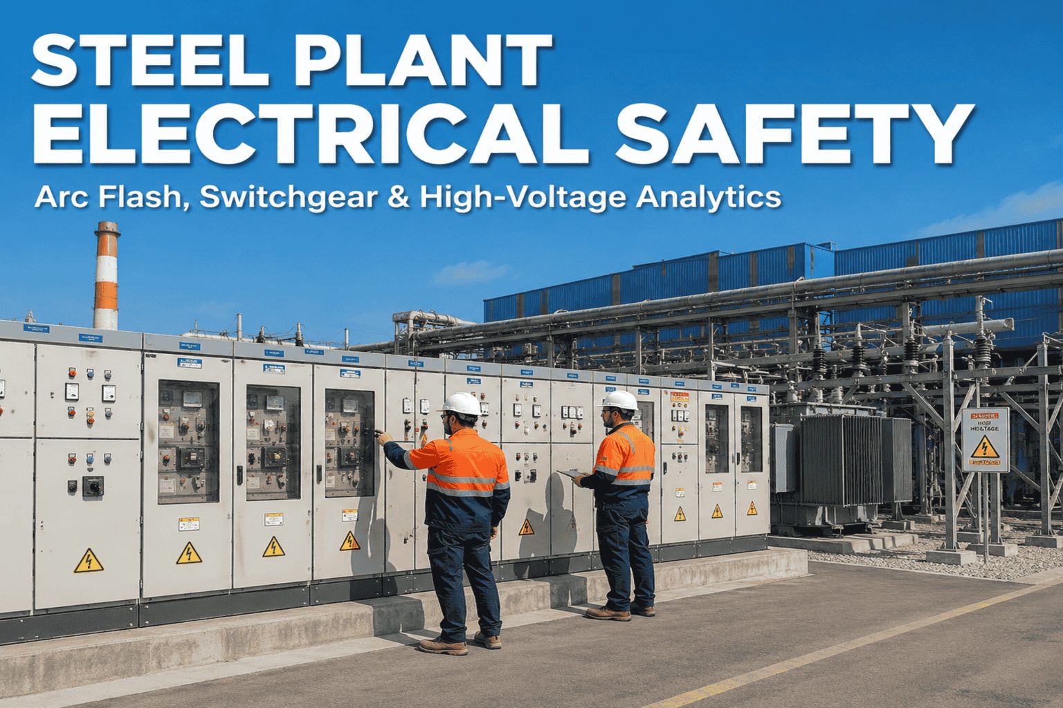
Steel Plant Electrical Safety
Arc Flash. Switchgear. High Voltage.
Zero Incidents.
A field-ready framework for NFPA 70E compliance, predictive electrical maintenance, and AI-powered safety management in modern steel manufacturing.
The Electrical Risk Landscape in Steel Manufacturing
Steel plants operate with electrical systems of extraordinary scale and complexity. A single electric arc furnace draws 40–150 MW during a heat cycle. Rolling mill drives operate at voltages up to 6.6kV. Continuous casting lines rely on hundreds of variable frequency drives (VFDs) running 24/7. This density of high-energy electrical equipment creates a risk profile that standard industrial safety frameworks are simply not designed to address.
$2B+
Annual arc flash incident cost (U.S. industry)
5–10x
Higher electrical incident rate vs. average industry
40%
Of electrical failures preceded by detectable warning signs
60%
Cost reduction achievable with predictive electrical maintenance
The Occupational Safety and Health Administration (OSHA) cites electrical hazards as a leading cause of workplace fatalities across heavy industry. In steel specifically, the combination of high incident energy levels, frequent switching operations, and aging switchgear infrastructure amplifies this risk. The regulatory framework—anchored by NFPA 70E (Standard for Electrical Safety in the Workplace) and OSHA 29 CFR 1910 Subpart S—demands documented, repeatable safety processes that most paper-based maintenance programs cannot reliably deliver.
Arc Flash Analysis: From Study to Living Document
An arc flash hazard analysis is the foundation of every compliant electrical safety program. NFPA 70E requires facilities to perform an arc flash risk assessment and update it whenever a major modification or renovation is made to the electrical system—and at minimum, every five years. In practice, many steel plants treat their arc flash study as a one-time event, then file it away. That approach creates both regulatory exposure and genuine physical risk.
One-line diagram validation — Confirm as-built accuracy of all feeders, buses, and protective devices before modeling begins.
Short-circuit analysis — Calculate available fault current at every bus and panel using IEEE 1584-2018 methodology.
Protective device coordination — Model upstream/downstream device coordination to confirm clearing times used in incident energy calculations.
Incident energy calculation — Determine cal/cm² values at working distances for all equipment where energized work may occur.
Hazard Risk Category assignment — Classify each work task by HRC (1–4) to determine required PPE levels per Table 130.5(C).
Arc flash labels on every panel — NFPA 70E 130.5(H) requires labels listing incident energy, working distance, limited/restricted approach boundaries, and minimum PPE.
Limited Approach Boundary — Defines the distance at which an unqualified person may not cross without escort; varies by voltage class.
Restricted Approach Boundary — Only qualified electrical workers with appropriate PPE and an energized electrical work permit may enter.
Arc Flash Boundary — The distance at which incident energy equals 1.2 cal/cm²—the threshold for a second-degree burn from an arc flash event.
Trigger-based updates — Any transformer replacement, feeder reconfiguration, or new large load addition must trigger a partial re-study of affected buses.
CMMS integration — Link arc flash study data directly to asset records so work orders auto-populate PPE requirements and approach boundaries for technicians.
5-year mandatory review — Schedule full system re-analysis as a recurring PM task in your CMMS to ensure no cycle is missed.
Version-controlled records — Maintain a traceable audit trail of every study revision, with timestamps and engineer sign-off stored digitally.
Managing arc flash compliance across a large steel facility? Book a session to see how iFactory links arc flash data directly to work orders and PPE requirements.
Switchgear & MCC Management: Predictive Over Reactive
Switchgear failure in a steel plant is rarely sudden. Thermal degradation, connection loosening, insulation tracking, and breaker mechanism wear all develop over months—and all produce measurable signals long before catastrophic failure. The challenge for most facilities is that detecting these signals requires systematic inspection programs that paper-based maintenance cannot reliably execute.
Reactive Approach
Annual visual inspections only
No thermal imaging schedule
Breaker testing on breakdown only
Paper-based inspection logs
Unplanned outages average 18+ hrs
Compliance gaps discovered at audit
VS
Predictive Digital Approach
Quarterly IR thermography per schedule
IoT partial discharge monitoring
Annual breaker trip-time testing in CMMS
Digital work orders with photo capture
Planned outages average under 4 hrs
Audit-ready reports generated in seconds
Switchgear & MCC Inspection Frequency Guide
Asset Type
Inspection Type
Frequency
Key Parameters
Standard Reference
Medium voltage switchgear (4–15kV)
Thermographic scan
Quarterly
Hot spots >15°C above ambient
NETA MTS, NFPA 70B
Low voltage MCCs
Visual + IR inspection
Semi-annual
Connection torque, corrosion, insulation
NFPA 70E 205.4
Circuit breakers (all classes)
Trip timing & contact resistance
Annual
Trip time within OEM spec ±10%
ANSI/IEEE C37.09
VFDs / soft starters
Cleaning & connection check
Semi-annual
DC bus voltage, harmonic levels
OEM recommendations
Bus bars & connections
Torque verification + IR
Annual
Torque per OEM spec, delta-T <10°C
NFPA 70B Ch. 9
Partial discharge (MV equipment)
PD monitoring / testing
Annual or continuous
PD level trending vs. baseline
IEC 60270
Transformer Maintenance: The Heart of Steel Plant Power Distribution
Steel plant transformers—ranging from main power transformers at the substation to furnace transformers rated 60–100 MVA—are among the most capital-intensive assets in the facility. Transformer failure rarely happens without warning; oil analysis, thermal monitoring, and load factor tracking consistently provide 3–12 months of advance notice for the failure modes that cause the most damage.
01
Dissolved Gas Analysis (DGA)
Sample transformer oil quarterly. Trending of key gases—hydrogen, acetylene, ethylene—identifies thermal faults, partial discharge, and arcing inside the tank months before failure.
Quarterly
02
Oil Quality Testing
Annual dielectric breakdown voltage, moisture (ppm), acidity, and interfacial tension tests determine oil condition and insulation degradation rate. Trending against IEEE C57.106 limits guides maintenance decisions.
Annual
03
Thermal Monitoring & Load Factor Tracking
Continuous top-oil and winding temperature monitoring via RTDs. Loading above nameplate for sustained periods accelerates insulation aging; log load factor daily and alert when above 90% nameplate for >4 hrs.
Continuous
04
Tap Changer Inspection
On-load tap changers (OLTCs) on furnace transformers execute thousands of operations per day. Inspect contact wear, oil contamination, and motor mechanism annually; replace contacts per OEM operation count.
Annual
05
Insulation Resistance & Power Factor Testing
Megger testing at scheduled outages confirms winding insulation integrity. Power factor (dissipation factor) trending detects moisture ingress and insulation aging not visible in DGA alone.
At outage
Want to build a transformer PM program that connects oil analysis results directly to work orders? Schedule a personalized assessment with our electrical maintenance experts.
Ready to Digitize Your Electrical Safety Program?
From arc flash labeling to switchgear PM schedules and transformer oil trending, iFactory gives your team the digital infrastructure to maintain NFPA 70E compliance continuously—not just at audit time.
In steel plants, cable systems carry power through some of the harshest industrial environments on earth—extreme heat, electromagnetic interference from furnace operations, vibration from rolling mills, and chemical exposure in pickling and galvanizing areas. Cable failures are a leading cause of both electrical fires and production outages. A systematic approach to cable management and earthing integrity is non-negotiable.
Cable System Management
Cable tray inspection: Check fill levels, tray integrity, and cable support every 6 months. Overcrowded trays trap heat and accelerate insulation degradation.
Insulation resistance testing: Annual megger testing on all medium voltage feeders; track IR values over time—a declining trend signals moisture ingress or insulation aging.
Thermal imaging of cable terminations: Loose or corroded terminations are hot spots waiting to become failures. Scan all MV terminations quarterly.
Cable age tracking in CMMS: Assign installation dates and expected service life to all cable segments; flag cables exceeding 20-year service life for engineering review.
Mechanical protection inspection: Verify conduit integrity, cable armoring, and mechanical protection in high-traffic areas, especially near crane ways and material handling equipment.
Earthing & Lightning Protection
Earth resistance testing: Measure ground electrode resistance annually using fall-of-potential or clamp-on method. Target <1 ohm for substation grounds; <5 ohm for equipment grounds per IEEE 142.
Ground connection integrity: Inspect all equipment grounding conductors for continuity, corrosion, and mechanical security every 6 months. Special attention to EAF electrode arms and furnace structures.
Touch and step potential survey: Conduct grounding system adequacy study (IEEE 80) when significant facility expansion occurs or after any major ground fault event.
Lightning protection inspection: Annual inspection of air terminals, down conductors, and ground connections per NFPA 780. Check bonding of all structural steel members to the lightning protection system.
Surge protective devices (SPDs): Inspect condition indicators on all SPDs quarterly; replace any SPD that has responded to a surge event before reinstating as protection is consumed.
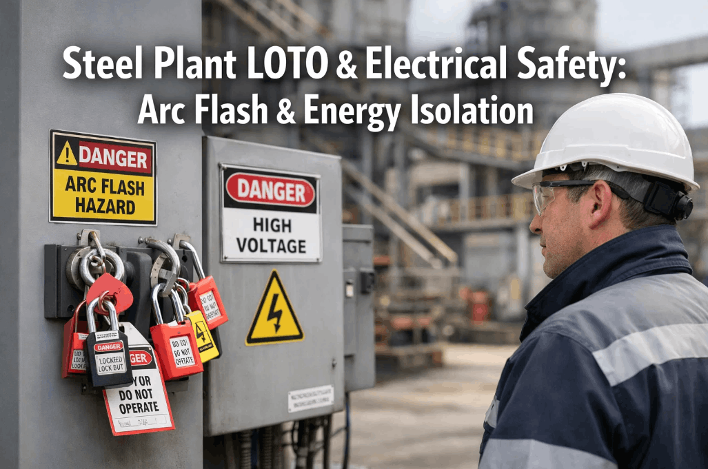
Electrical PPE Requirements and Compliance Management
Personal protective equipment is the last line of defense in electrical safety—it is not the primary protection strategy. NFPA 70E is clear: establishing an electrically safe work condition through de-energization, lockout/tagout, and verification of absence of voltage is always preferred over working energized. When energized electrical work is justified, the PPE requirements derived from the arc flash hazard analysis must be rigorously enforced and documented.
HRC 1
1.2–4 cal/cm²
Arc-rated shirt & pants (min. 4 cal/cm²)
Safety glasses
Leather gloves (Class 00 or 0)
Hard hat
120/208V panels, typical LV work
HRC 2
4–8 cal/cm²
Arc-rated shirt, pants & jacket (min. 8 cal/cm²)
Arc-rated face shield or flash suit hood
Class 0 or 00 rubber insulating gloves with leather protectors
Arc-rated hard hat liner
480V MCC work, LV switchgear racking
HRC 3
8–25 cal/cm²
Arc flash suit (min. 25 cal/cm² system rating)
Flash suit hood with arc-rated face shield
Class 2 rubber insulating gloves with leather protectors
Full body arc-rated protection, cotton underwear only
13.8kV switching, EAF secondary bus work
Note: Incident energy above 40 cal/cm² requires engineering controls to reduce hazard—PPE alone is not a compliant solution. Energized electrical work permits (EEWPs) must be issued for all HRC 2 and above tasks, documenting justification for energized work, risk assessment, and PPE selection per NFPA 70E 130.2.
NFPA 70E
Electrical safety in the workplace
OSHA 1910 Subpart S
Electrical standards for general industry
IEEE 1584-2018
Arc flash hazard calculations
NFPA 70B
Recommended practice for electrical equipment maintenance
Expert Review: What Electrical Safety Leaders Are Getting Wrong
"The most common failure pattern I see in steel plant electrical programs isn't ignorance of NFPA 70E—it's the gap between policy and execution. A facility will have an excellent written arc flash program and a five-year-old study that doesn't reflect three major transformer replacements and a mill expansion. They'll have PPE on the shelf that hasn't been inspected or recertified in two years. The documentation exists; the living program doesn't. Digital CMMS with PM scheduling tied directly to the arc flash study is the only scalable answer for facilities operating at this voltage and complexity level. When a technician opens a work order and the system tells them the incident energy, the required PPE, and the last time that breaker was tested—that's when compliance becomes operational rather than aspirational."
Electrical Safety DirectorIntegrated Steel Manufacturing Facility — U.S. Midwest
Conclusion
Electrical safety in steel plants is a discipline that demands precision, consistency, and scalability that paper-based programs simply cannot deliver. The five pillars—arc flash analysis kept as a living document, systematic switchgear and MCC management, proactive transformer care, rigorous cable and earthing integrity, and properly managed PPE compliance—are not independent checkboxes. They are an integrated system. When one element degrades, the entire risk profile shifts.
The facilities that achieve sustained NFPA 70E compliance and genuine zero-incident electrical programs share a common characteristic: they have embedded their electrical safety requirements directly into their operational workflow through digital CMMS platforms. Work orders carry PPE requirements. PM schedules reflect arc flash study findings. Audit reports generate in seconds, not days. That is what separates compliant programs from safe programs—and in steel manufacturing, the difference is measured in lives and operating hours.
Build Your Electrical Safety Program on a Digital Foundation
From arc flash analysis integration to switchgear PM scheduling and real-time compliance tracking, iFactory provides steel manufacturers the tools to maintain NFPA 70E compliance continuously—and prove it instantly at audit time.
QHow often must a steel plant update its arc flash hazard analysis?
NFPA 70E requires the arc flash risk assessment to be updated whenever a major modification or renovation is made to the electrical distribution system, and at minimum every five years. In practice, steel plants should trigger a partial re-study any time a transformer is replaced or rerated, a new large motor load is added, feeder routing changes significantly, or a protective relay or breaker is replaced with a different model. Tying re-study triggers to a CMMS change management workflow is the most reliable approach to keeping the study current.
QWhat is the most dangerous electrical task in a steel manufacturing environment?
Racking medium voltage circuit breakers in or out of service position on energized switchgear consistently ranks as the highest incident energy task in steel plant electrical programs, often exceeding 40 cal/cm². Electric arc furnace secondary bus work and main substation switching are similarly high-risk. The combination of high available fault current, large bus geometry (which increases arc flash energy), and the necessity of performing these operations during production—when de-energizing is operationally difficult—creates conditions where PPE alone is insufficient. Remote racking tools and remote switching mechanisms are the engineering control solution of choice for these tasks.
QWhat electrical maintenance data should a CMMS capture for NFPA 70E compliance?
A CMMS supporting NFPA 70E compliance should capture: arc flash study incident energy and PPE requirements linked to each asset, energized electrical work permit records, all inspection and test results (breaker trip times, insulation resistance values, thermographic findings, oil analysis results) with timestamps and technician credentials, PPE inspection and recertification dates, worker qualification records for electrical tasks, and LOTO procedure documentation linked to each asset. The ability to generate a complete maintenance history for any asset within seconds is the practical compliance test—if it takes hours, the documentation system is not adequate for audit purposes.
QHow does predictive maintenance reduce electrical safety risk in steel plants?
Predictive electrical maintenance reduces safety risk through two primary mechanisms. First, it eliminates the conditions that create the most hazardous energized work scenarios—equipment that fails unexpectedly forces reactive maintenance under time pressure, which is when most electrical incidents occur. By detecting degradation early, facilities can schedule interventions during planned outages with proper preparation, PPE staged, and second workers in attendance. Second, continuous monitoring of critical equipment parameters (partial discharge, thermal anomalies, oil gas concentrations) provides objective data that allows maintenance teams to assess risk quantitatively rather than relying on time-based schedules alone, optimizing both safety and maintenance resource allocation.
QWhat are the OSHA penalties for electrical safety violations in industrial facilities?
OSHA classifies electrical safety violations under 29 CFR 1910 Subpart S. As of the current penalty structure, serious violations carry maximum penalties of $16,131 per violation; willful or repeated violations can reach $161,323 per violation. Following a fatality, OSHA investigations routinely result in multiple citations across training, PPE, lockout/tagout, and hazard assessment requirements—meaning total penalty exposure in a serious incident can exceed $1 million. Beyond direct OSHA penalties, facilities face workers' compensation liability, civil litigation, increased insurance premiums, potential production shutdowns during investigation, and reputational damage with customers and insurers. The financial case for preventive electrical safety investment is overwhelmingly positive when modeled against incident probability and consequence.
function SE1switchTab(btn, id) {
var wrap = btn.closest('.SE1-tabs-wrap');
wrap.querySelectorAll('.SE1-tab').forEach(function(t){t.classList.remove('SE1-tab-active')});
wrap.querySelectorAll('.SE1-tab-panel').forEach(function(p){p.classList.remove('SE1-panel-active')});
btn.classList.add('SE1-tab-active');
document.getElementById('SE1-tab-' + id).classList.add('SE1-panel-active');
}
function SE1toggleFaq(header) {
var item = header.closest('.SE1-faq-item');
var isOpen = item.classList.contains('SE1-faq-open');
document.querySelectorAll('.SE1-faq-item').forEach(function(el){el.classList.remove('SE1-faq-open')});
if (!isOpen) item.classList.add('SE1-faq-open');
}