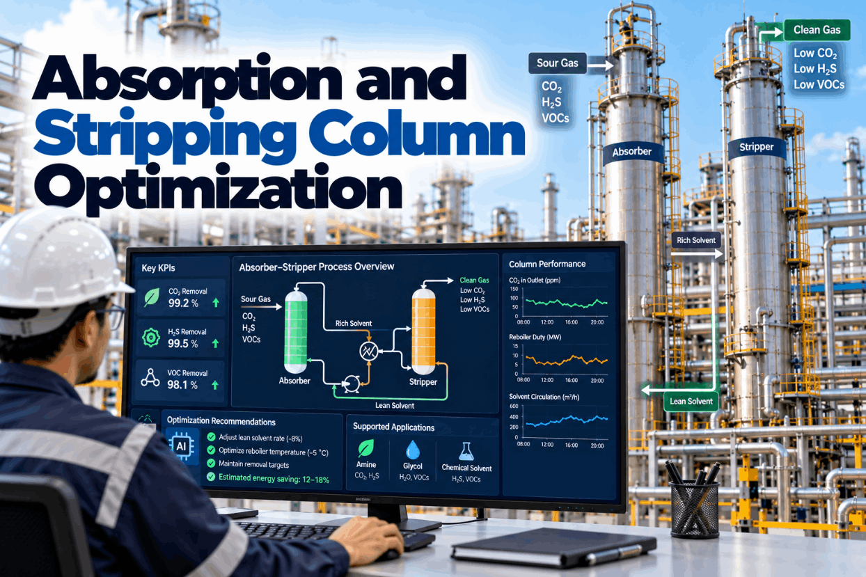
Absorption and stripping columns remove carbon dioxide, hydrogen sulfide, water and volatile organics from gas streams across chemical plants, refineries and gas processing. Amine units, glycol dehydrators and chemical scrubbers all work on the same principle: a solvent picks up the unwanted component in an absorber and gives it up again in a regenerator. The difficulty is running them well. Too little solvent circulation and the treated gas goes off spec; too much and reboiler steam is wasted. Rich loading that creeps up brings corrosion, and contaminants bring foaming and degradation. This guide covers how the loop works, amine and glycol choices, loadings, regenerator energy, foaming, heat-stable salts and how continuous optimization holds the unit at its best point. To see your unit’s operating window, book a short walkthrough.
Absorption and Stripping Column Optimization: Amine, Glycol and Scrubber Units at Their Best Point
Circulation, lean loading and reboiler duty held at the minimum that keeps treated gas on spec, with rich loading, foaming and solvent health watched before they cost a trip or a corrosion failure.
Why Gas Treating Units Run Away From Their Best Point
An absorber and regenerator loop has one job: meet a treated gas specification at the lowest cost. In practice, most units run with generous margins. Operators raise circulation and reboiler steam to stay safely on spec, because an off-spec event is visible and costly while wasted steam is quiet. Over months, those margins become the normal way of running.
Regeneration energy is the main operating cost. Pilot testing of 30 wt% monoethanolamine (MEA) for carbon dioxide capture, published in Applied Energy, reported regeneration energy of about 3.6–3.8 GJ per tonne of carbon dioxide, with an optimum near 3.46 GJ/t at the best lean loading. Small changes in lean loading and circulation move that number noticeably.
Margins also hide risks. Rich loading that creeps up during high throughput accelerates corrosion. Contaminants build up and cause foaming. Heat-stable salts accumulate slowly until capacity has fallen and corrosion has started. Each of these shows in the data long before it becomes an incident.
Continuous optimization holds the unit close to its best point while watching those risks. We can review your unit data on a call.
The Absorber and Regenerator Loop
All solvent-based gas treating units share the same loop.
Three variables decide most of the unit’s performance: solvent circulation rate, lean loading and solvent strength. Circulation and strength set how much acid gas the solvent can carry. Lean loading, set by reboiler duty, sets how clean the treated gas can be and how much steam is used.
Finding the best combination for today’s gas is what optimization does. See the operating window in a demo.
Amine and Glycol Choices
Different solvents suit different jobs. Typical strengths quoted in industry references are shown below; each plant sets its own limits.
| Solvent | Typical strength | Typical use | Notes |
|---|---|---|---|
| MEA | About 20 wt% for H2S and CO2, about 30 wt% for CO2 only | CO2 removal, carbon capture | Reactive, higher regeneration energy, degrades |
| DEA | 25–35 wt% | Refinery and gas plant treating | Less reactive than MEA |
| MDEA | 30–55 wt% | H2S treating with partial CO2 slip | Lower regeneration energy, often activated for CO2 |
| DGA | 40–50 wt% | Gas treating | High concentration, low circulation |
| TEG | About 98.8–99.9 wt% lean | Natural gas dehydration | Stripping gas needed for the highest purity |
| Caustic or chemical scrubbers | Varies | Acid gas and VOC scrubbing | Once-through or regenerated, depending on chemistry |
MDEA is popular where hydrogen sulfide must be removed while some carbon dioxide can pass through, because it reacts more slowly with carbon dioxide and needs less regeneration energy. Activated MDEA blends add a faster-reacting amine when carbon dioxide must be removed too.
Solvent strength drifts in operation through water balance and losses. Running weaker than intended reduces capacity and raises loading; running stronger can increase corrosion and viscosity. Regular lab analysis, linked to the unit model, keeps strength where it should be.
Our engineers can review whether your solvent strength and type still fit your gas.
Lean Loading, Rich Loading and Reboiler Steam
Loading links treating performance, energy and corrosion. Lean loading drives energy; rich loading drives corrosion.
Illustrative. The right lean loading depends on solvent, gas and specification and is set from your own unit model.
Rich loading limits are specific to each unit. A Digital Refining case study of an MEA unit described a maximum rich loading of 0.35 mol/mol for carbon steel equipment, while a gas plant optimization study for an activated MDEA unit used 0.53 mol/mol as its limit. The limit depends on solvent, metallurgy, temperature and velocity, so it should come from the plant’s own corrosion assessment.
Optimization works inside both limits at once: lean loading high enough to avoid wasting steam, low enough to keep gas on spec, and rich loading safely below the corrosion limit. Circulation is the lever that connects them.
Most units have room to save steam inside their existing limits. Ask our team to estimate yours.
Foaming: Causes, Signals and Response
Foaming is one of the most disruptive problems in amine units. It reduces capacity, carries solvent into downstream equipment and can push treated gas off spec within minutes.
Condensed hydrocarbons in the feed gas lower surface tension and stabilize foam.
Iron sulfide and other fines stabilize foam bubbles.
Heat-stable salts and amine degradation products raise foaming tendency.
Well treating chemicals, corrosion inhibitors and even excess antifoam.
A sudden rise in absorber or regenerator differential pressure.
Erratic sump level and solvent carryover to knock-out drums.
Antifoam treats the symptom; removing the cause is the lasting fix. Better inlet separation, filtration and reclaiming reduce foaming tendency. Engineering sources note that too much antifoam can itself promote foaming, so dosing should be measured, not habitual.
Early detection gives operators time. Differential pressure, level and treated gas analysis together show a foaming event starting, often minutes before the specification is lost, which is enough time to cut throughput or dose antifoam deliberately.
Linking foaming events to their causes shows which ones recur. We include that analysis in every rollout.
Heat-Stable Salts, Degradation and Glycol Health
Solvent quality declines slowly and silently. Tracking it prevents capacity loss and corrosion.
Formed when amine reacts with acids stronger than CO2 or H2S. Regeneration cannot remove them, so they build up and tie up amine.
Industry references suggest keeping MDEA heat-stable salts below about 2 wt% and reclaiming at about 4 wt% total anions; plants set their own limits.
High reboiler temperatures and oxygen ingress break down amine, raising makeup and foaming tendency.
TEG decomposes above about 404 °F, so reboiler temperature is held below that, typically near 400 °F, giving about 98.8 wt% lean glycol.
Reaching purities up to about 99.9 wt% for low dew points needs stripping gas, at a fuel cost.
Bryan Research and Engineering cites about 3 gallons of TEG per pound of water removed as a typical circulation rate.
Lab data and process data together tell the story. Rising heat-stable salts with rising corrosion probe readings, or rising glycol losses with higher contactor temperature, point directly to the cause.
Solvent health becomes a scheduled task instead of a surprise. Discuss it with our specialists.
Margin-Based Operation Versus Continuous Optimization
The difference between running on margins and running on a model shows in steam use and risk.
- Circulation set high and left there
- Reboiler duty set for worst-case gas
- Rich loading checked occasionally
- Foaming handled after it starts
- Solvent analysis reviewed monthly
- Steam use treated as fixed
- Circulation matched to current gas
- Lean loading held at the spec target
- Rich loading kept below site limit
- Foaming precursors watched
- Solvent health trended with process data
- Steam per tonne treated tracked daily
Optimization does not remove safety margins. It replaces vague margins with explicit limits, such as the maximum rich loading and the treated gas specification, and runs as close to the economic point as those limits allow.
Recommendations start in advisory mode, reviewed by your engineers. See how in a session.
Absorber and Regenerator Checklist
Use this checklist to set up continuous optimization on a gas treating unit.
Most units already measure what is needed. Combining it into one view is the first step of an absorber review.
What Absorber Optimization Is Worth
Value comes from steam saved and incidents avoided.
Regeneration energy dominates the operating cost of amine units, which is why even modest improvements in lean loading control matter. The MEA pilot data show the spread between typical and optimal operation; your unit’s own data will show where it sits on that range.
A few weeks of unit data are usually enough for a first estimate. Book one with our advisors.
How iFactory Delivers Absorber Optimization
Calibrated on your own absorber and regenerator data.
Circulation and lean loading for current gas.
Rich loading tracked against your site limit.
Differential pressure, level and precursors together.
Lab results trended with process conditions.
Steam per tonne treated reported daily.
It runs on premises beside your DCS and historian. Share a month of unit data and we will show your operating window in a working session.
Find the Steam Your Regenerator Does Not Need
Share a month of absorber, regenerator and lab data. We build the operating window, check rich loading against your limits and estimate the steam saving at your current specification.
Rich loading has climbed to 0.46 mol/mol against a site corrosion limit of 0.50. Circulation can rise 6% within pump limits, which restores margin at a small reboiler steam cost.
Rich Loading Caught During a Rate Increase
This exchange shows how a process engineer might use iFactory.
iFactory ships as a pre-configured NVIDIA AI server, racked and ready with the absorber and regenerator optimization models loaded. Rack it, plug in power and Ethernet, and the AI is live on your network. Our scope covers data connections across process units, utilities and the control room, DCS, PLC/SCADA, historian, LIMS and CMMS integration, cabling and network setup, operator and engineer training, and 24×7 remote monitoring. Recommendations run in advisory mode first, and nothing writes to your control system without your management of change approval.
Server installed, DCS and historian links live, historical process, lab and maintenance data loaded.
Models calibrated on your own unit data, then run in advisory mode on one unit with your process engineers reviewing every recommendation.
Rollout to the agreed units under your management of change, operator and engineer training, and 24×7 remote monitoring in place.
Software, server and integration come as one package. For pricing on your site, contact our sales team.
Frequently Asked Questions
Reboiler steam for regeneration. Pilot testing of 30 wt% MEA reported about 3.6–3.8 GJ per tonne of CO2, with an optimum near 3.46 GJ/t at the best lean loading.
Mainly corrosion. Limits are unit-specific: one MEA case study used 0.35 mol/mol for carbon steel, while an activated MDEA study used 0.53 mol/mol. Plants set their own limit from metallurgy and conditions.
Liquid hydrocarbons, fine solids such as iron sulfide, degradation products and heat-stable salts, and surfactants including excess antifoam.
Salts formed when amine reacts with acids stronger than CO2 or H2S. Regeneration cannot remove them, so they reduce capacity and raise corrosion unless reclaimed.
By regenerating glycol to about 98.8 wt% in the reboiler, below its decomposition temperature, and using stripping gas when higher purity is needed for lower dew points.
A first unit can typically be optimized within a 6–12 week rollout, starting in advisory mode. Plan it with our engineers.
Run Your Gas Treating Unit at Its Best Point
iFactory matches circulation and reboiler duty to today’s gas, keeps rich loading inside your limits and watches foaming and solvent health, cutting steam without risking the specification.
Illustrative, indexed to week 1. Steam fell as lean loading was held to target instead of over-stripping.