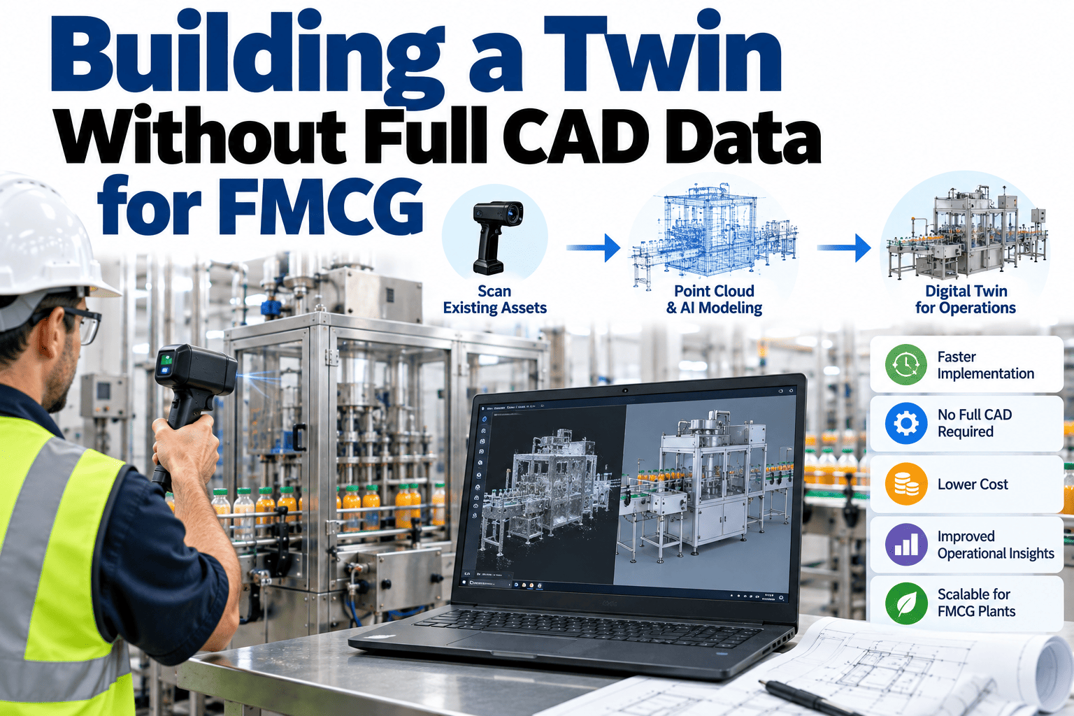
Most digital twin projects stall on the same assumption: that somewhere in a filing cabinet or a supplier archive, complete CAD drawings exist for every filler, capper, and conveyor on the line. For FMCG plants running equipment that's been retrofitted, rebuilt, or bought secondhand over fifteen or twenty years, that assumption is usually wrong. Drawings go missing when a machine changes hands, OEMs discontinue support for older model lines, and years of field modifications drift the physical asset further from whatever paperwork survived. None of that has to stop a digital twin from getting built. iFactory captures the missing geometry directly from the physical equipment using laser scanning, photogrammetry, and reference-model techniques, so the twin gets built from what's actually on your floor — see how the scan-based approach works on your own equipment.
No Drawings? The Equipment Itself Is the Source of Truth.
When OEM CAD is missing, outdated, or doesn't match what's actually installed, iFactory builds your digital twin directly from the physical asset — using laser scanning, photogrammetry, and reference-model techniques matched to what each machine actually needs.
The CAD Gap Is the Rule on FMCG Lines, Not the Exception
It's tempting to treat a missing CAD file as an unusual problem specific to one old machine, but on a typical FMCG packaging line it's closer to the default state. Equipment gets bought secondhand, rebuilt after a major overhaul, or modified in the field to handle a new product format, and each of those events widens the gap between the drawing on file and the machine standing on the floor.
None of these situations are unusual, which is exactly why waiting for complete CAD before starting a twin project leaves most FMCG plants waiting indefinitely. The equipment itself has always been the more reliable source of truth — the question is how to capture its actual geometry efficiently.
There's also a subtler version of the gap that's worth naming directly: a drawing can exist and still be wrong. A filed CAD model that predates a decade of field modifications isn't missing, it's misleading, which in some ways is a harder problem than having no drawing at all, because a team can be working confidently from a document that no longer matches the machine in front of them.
Laser Scanning, Photogrammetry, and Reference Models
There isn't one correct way to capture missing geometry, there's a set of techniques with different tradeoffs in accuracy, cost, and speed, and the right one depends on what the asset is and how precisely the twin needs to represent it.
These techniques aren't mutually exclusive. A common and often more cost-effective approach combines them — photogrammetry for the overall shape and layout, laser scanning targeted only at the handful of dimensions where precision actually matters for the maintenance or simulation use case.
Cost and speed both favor a hybrid strategy in practice. A full facility laser scan of a large FMCG line can run into significant expense given the equipment and specialized training involved, while photogrammetry has become dramatically cheaper as high-resolution cameras and processing power have improved. Reserving the more expensive method for the specific dimensions that actually justify its cost is usually the difference between a capture project that fits the budget and one that doesn't.
Find out which capture method fits your equipment
iFactory can assess your specific assets — age, condition, and what documentation survives — and recommend the right combination before you commit to anything.
Not Every Asset Needs Millimeter Precision
The instinct when geometry is missing is to reach for the most precise capture method available, but that's often the wrong economic call. The right question isn't "how accurate can we get," it's "how accurate does this specific use case actually require."
| Use Case | Precision Needed | Typical Capture Method |
|---|---|---|
| Layout & clearance planning | Centimeter-level, overall shape matters most | Photogrammetry, fast and low-cost |
| Change-part or tooling fit | Millimeter-level, exact clearances critical | Targeted laser scan of the specific interface |
| Failure simulation on a known component | Moderate, physics-based behavior matters more than exact surface geometry | Reference model adjusted to field measurements |
| As-built documentation for compliance | High, needs to match physical reality closely | Full laser scan point cloud |
| Virtual line testing across multiple assets | Moderate, consistent representation across the line matters most | Photogrammetry plus reference models, standardized |
Matching the method to the actual requirement is what keeps a scan-based twin project affordable across an entire line, rather than treating every asset as if it needs the same exhaustive, expensive capture process regardless of what the twin will actually be used for.
This same logic explains why an all-laser-scan approach, however appealing for its precision, is often the wrong default for an entire FMCG line. Most of what a twin needs to represent is overall shape, layout, and the behavior that drives failure simulation — genuine sub-millimeter geometric precision is the exception on most assets, not the rule, and treating it as a blanket requirement inflates cost without a matching gain in usefulness.
What Happens After the Scan
Raw capture data — whether a point cloud or a set of photographs — isn't a usable twin on its own. It has to be processed into clean geometry, then connected to real sensor data before it can support failure simulation or feed a CMMS.
The geometry is the foundation, but it's the connection to live operating data that makes the twin useful for failure prediction and virtual line testing. A beautifully scanned but disconnected 3D model is still just a picture — the value comes from what runs on top of it.
That validation step deserves particular attention, because it's the point where scan-based capture proves itself trustworthy or reveals a problem worth fixing before the twin goes any further. Spot-checking a handful of critical dimensions against the physical machine takes far less time than reprocessing a poorly calibrated capture later, once live sensor data is already streaming into a geometry that quietly doesn't match reality.
Scan-Based Capture Doesn't Have to Slow the Project Down
A common worry is that building a twin from scratch, without CAD to start from, adds months to the deployment. In practice, capture is usually one of the faster phases of the project once the right method is matched to each asset, because it's bounded, physical work rather than an open-ended search for documentation that may not exist.
The absence of CAD is a genuine obstacle, but it's a solvable one with a known set of techniques, not a reason to postpone the twin project until documentation surfaces that, on most older FMCG lines, never will.
Plants that wait for missing documentation to reappear are, in effect, betting against fifteen years of evidence that it won't. The more productive framing is that the drawing was never really the asset that mattered — the machine on the floor was always the thing worth modeling, and it has been available to capture the entire time.
Delivered as a Working Twin, Not a Point Cloud Handoff
iFactory doesn't stop at delivering scan data and leaving your team to build the twin themselves. The capture, processing, validation, and live-data connection are delivered as one turnkey engagement, so what you end up with is a working system.
Scope covers the capture work itself, geometry processing, PLC and SCADA integration for live data, and operator training, so the missing CAD never becomes the reason a digital twin project stays stuck at the planning stage. Trusted by 1000+ clients with 99.9% uptime, the deployment is built to fit around a live FMCG production line.
What FMCG Plants Ask Before Building a Twin Without CAD
Build the Twin From What's Actually There
iFactory captures the geometry your CAD archive is missing directly from the physical equipment, using laser scanning, photogrammetry, and reference models matched to what each asset actually needs.