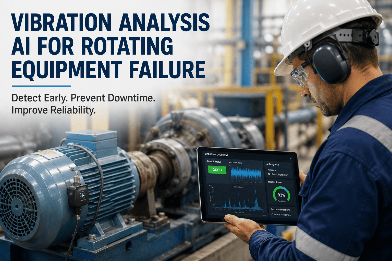
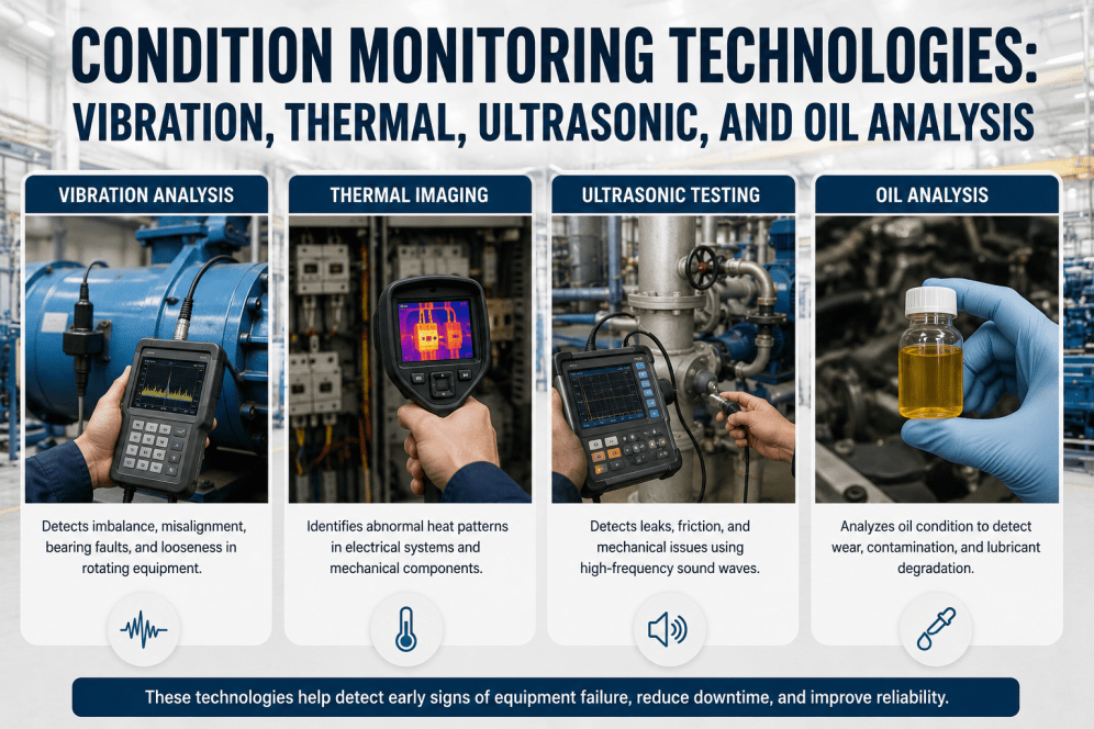
Selecting the wrong sensor for a monitoring application does not just waste money. The correct sensor type for each equipment and fault category is determined by the physics of what you are trying to detect: a bearing defect frequency at 4,000 Hz cannot be found with a 10 Hz temperature sensor, and a thermal overload cannot be diagnosed from a vibration spectrum alone. iFactory's deployment team has standardized sensor selections across hundreds of manufacturing plant deployments, matching sensor type, specifications, mounting method, and connectivity protocol to the specific fault signatures that matter for each equipment category. This guide documents those selections for the five core sensor types used in industrial predictive maintenance monitoring programs. Book a free sensor audit for your plant's monitoring program today.
iFactory integrates five core sensor types for manufacturing equipment monitoring: triaxial MEMS vibration sensors (10 Hz to 10 kHz, OPC-UA or Bluetooth 5.0 output) for rotating equipment bearing and gear fault detection; PT100 and thermocouple temperature sensors for thermal trending; pressure transmitters (4-20mA or HART) for hydraulic, pneumatic, and steam system monitoring; current transformer (CT) clamps for motor load trending and stator fault detection; and ultrasonic sensors (35-45 kHz) for compressed air leak and partial discharge monitoring. All five sensor types connect to iFactory's on-premise edge gateway via standard industrial protocols with zero DCS modification required.
The 5 Core IoT Sensor Types: Specifications, Mounting, and iFactory Integration
Each sensor type has a specific fault detection role, operating range, mounting method, and connectivity requirement. Selecting outside the specified range for the target fault type produces data that the AI cannot use for accurate fault detection. Book a demo to see iFactory's sensor integration configured for your specific equipment models.
Equipment-to-Sensor Selection Matrix
The table below maps each major equipment category in a manufacturing plant to the recommended sensor types, with the specific fault each sensor detects for that equipment. Use this as the starting point for specifying iFactory sensor deployments.
| Equipment Type | Vibration | Temperature | Pressure | Current (CT) | Ultrasonic |
|---|---|---|---|---|---|
| Electric motors (all types) | Bearing faults, rotor imbalance, misalignment | Bearing housing, winding thermal overload | Not primary | Load trending, rotor bar faults (MCSA), stator faults | Bearing lube check only |
| Centrifugal pumps | Bearing, cavitation (broadband), impeller wear (vane pass freq) | Bearing housing, seal housing temperature | Suction and discharge pressure for performance curve | Motor load trending vs flow | Not primary |
| Gearboxes | Gear mesh frequency, bearing defect frequencies, cepstrum | Gearbox housing, oil sump temperature | Not primary | Drive motor load for overloading and efficiency trending | Not primary |
| Hydraulic systems | Pump bearing only | Reservoir and return line temperature trending | System, circuit, and cylinder pressure analytics | Motor load for pump efficiency tracking | Not primary |
| Compressed air systems | Compressor bearings only | Compressor outlet temperature | System pressure, receiver pressure, circuit pressure | Compressor motor load for demand analytics | Leak detection, steam trap monitoring |
| Industrial boilers | Not primary | Stack temp, tube metal temp, feedwater, steam temperature | Steam pressure, feedwater pressure, drum pressure | FD/ID fan motors only | Steam trap monitoring on distribution |
| Power transformers | Not primary | Tank surface, bushing terminals, top-oil temperature | Not primary | Load current for thermal life model | Partial discharge at inspection ports and bushing caps |
| Conveyors and drive systems | Drive bearings, idler bearings, gearbox | Drive motor bearing temperature | Not primary | Drive motor load for belt tension and jam detection | Not primary |
Green = primary recommendation. Yellow = secondary or optional. No = not recommended as primary sensor for this equipment type.
iFactory's pre-deployment assessment produces a complete sensor specification: type, model, mounting method, connection point, cable run, and gateway integration for every asset in your monitoring program. No guesswork. No overspecification. Sensor procurement starts from a validated list.
iFactory vs Competing IoT Monitoring Platforms
Sensor selection is only as valuable as the platform that receives and interprets the data. iFactory's edge gateway accepts all five sensor types through standard industrial protocols, applying AI fault detection models that are calibrated to each sensor type's output characteristics without manual configuration. Book a demo to see iFactory's sensor integration configured for your equipment list.
| Capability | iFactory | TRACTIAN | Augury | MaintainX | Siemens Insights Hub | Fiix (Rockwell) | Limble CMMS | C3 AI Mfg |
|---|---|---|---|---|---|---|---|---|
| Sensor Integration Breadth | ||||||||
| Multi-sensor type support (vib, temp, pressure, current, ultrasonic) | All 5 types, unified AI model | Vibration + temperature (proprietary sensors) | Vibration + ultrasonic (proprietary sensors) | No sensor layer | Via third-party connectors | No sensor layer | No sensor layer | Via data connectors |
| Third-party sensor compatibility (any 4-20mA or OPC-UA) | Any standard industrial sensor | Proprietary sensors required | Proprietary sensors required | No sensor layer | Siemens sensors preferred | No sensor layer | No sensor layer | Via data platform |
| MCSA (motor current signature analysis) | 2 kHz+ sampling, rotor bar fault detection | No | No | No | Via SINAMICS drives only | No | No | Via data connectors |
| High-frequency pressure spike capture (100 Hz+) | For hydraulic water hammer detection | No | No | No | Via SCADA integration | No | No | Via connectors |
| Platform and Deployment | ||||||||
| On-premise edge gateway (no cloud dependency) | Full on-premise AI, air-gap available | Cloud primary | Cloud primary | Cloud SaaS | Cloud or hybrid | Cloud SaaS | Cloud SaaS | Cloud primary |
| Auto work order from sensor alert | Full WO: asset, fault, sensor, action, parts | Alert only | Alert only | Yes (manual trigger) | Via SAP PM | Yes | Yes | Via CMMS |
Based on publicly available documentation as of Q1 2025. Verify capabilities with each vendor before procurement decisions.
Regional Compliance: IoT Sensor Installation and Data Security Standards
Industrial IoT sensor deployments must meet both electrical safety installation standards and cybersecurity requirements for OT data handling. iFactory's sensor architecture complies with all major regional frameworks without cloud data transfer.
| Region | Key Standards | IoT and OT Compliance Requirement | iFactory Coverage |
|---|---|---|---|
| USA | NIST SP 800-82 (OT security) / NIST SP 800-213 (IoT device cybersecurity) / NEC Article 500/501 (hazardous area sensors) / UL 508A (industrial control panels) / ISA/IEC 62443 / NERC CIP (if grid-connected) | NIST 800-82 OT network segmentation for IoT sensor gateways, NEC 500/501 sensor ratings for hazardous area installations, UL 508A-compliant panel integration for sensor inputs, ISA/IEC 62443 security zones for sensor networks | NIST 800-82 OT-segmented sensor network, NEC hazardous area compliant sensor options, UL 508A edge gateway panels, IEC 62443 zone architecture, NERC CIP perimeter deployment for BES assets |
| UAE | ADNOC cybersecurity standards / UAE National Cybersecurity Strategy / IEC 62443 / ATEX / IECEx (for hazardous area) / OSHAD-SF / UAE data localization / ISO 27001 | ADNOC OT cybersecurity compliance for IoT sensor deployments, IECEx/ATEX certification for sensors in classified areas, UAE data localization for sensor monitoring data, IEC 62443 OT security zone implementation | ADNOC-compliant on-premise deployment, IECEx/ATEX sensor options for Ex zones, UAE data localization (all data on-premise), IEC 62443 security architecture, Arabic platform support |
| UK | ATEX Directive 2014/34/EU (retained in UK) / IEC 62443 / UK NCSC OT security guidance / DSEAR (hazardous area) / BS EN 60079 (Ex equipment) / Cyber Essentials / ISO 27001 | ATEX/Ex sensor certification for DSEAR hazardous areas, NCSC OT cybersecurity guidance for industrial IoT, IEC 62443 OT security zones, Cyber Essentials compliance for IoT network components | ATEX/UKCA Ex sensor options, DSEAR-compliant hazardous area installations, NCSC and IEC 62443 OT security, on-premise architecture eliminates cloud data transfer compliance concerns |
| Canada | CSA C22.1 (Canadian Electrical Code) / CSA 60079 (hazardous area) / PIPEDA (privacy) / IEC 62443 / CCCS OT security guidance / CSA Z1000 | CSA C22.1-compliant sensor installations, CSA 60079 Ex-rated sensors for hazardous area, PIPEDA-compliant monitoring data handling, CCCS OT cybersecurity guidance for industrial IoT | CSA C22.1 and CSA 60079 compliant installations, PIPEDA on-premise data compliance, CCCS OT security architecture, bilingual (EN/FR) documentation, IEC 62443 security zones |
| Germany / EU | ATEX Directive 2014/34/EU / EU Machinery Directive / IEC 62443 / GDPR / EU NIS2 Directive / EN 60079 (Ex equipment) / BSI IT-Grundschutz / IEC 61010 (safety for industrial equipment) | ATEX Ex-rated sensors for classified areas, GDPR-compliant on-premise sensor data handling, NIS2 OT cybersecurity for critical infrastructure, IEC 62443 zone and conduit model implementation, BSI IT-Grundschutz for OT environments | EU data residency available, GDPR on-premise architecture, ATEX Ex sensor options, NIS2 and IEC 62443 OT security, BSI IT-Grundschutz compliance documentation |
| Australia | AS/NZS 60079 (hazardous area, adopts IEC) / WHS Act / ASD Essential Eight (IoT cybersecurity) / AS/NZS 3000 (wiring rules) / IEC 62443 / Privacy Act 1988 / ISO 27001 | AS/NZS 60079-compliant Ex sensors for hazardous areas, ASD Essential Eight IoT cybersecurity controls, WHS-compliant sensor installation records, Privacy Act-compliant sensor data handling | AS/NZS 60079 Ex sensor options, ASD Essential Eight OT security controls, WHS installation documentation, Privacy Act on-premise data compliance, IEC 62443 architecture, ISO 27001 alignment |
iFactory's sensor network architecture satisfies hazardous area, OT cybersecurity, and data localization requirements across every region from day one. Your IoT monitoring deployment is compliant by architecture, not by remediation after the fact.
Results: Manufacturing Plants Running iFactory Sensor Networks
iFactory's baseline learning period after sensor deployment is 7 to 21 days per asset. First actionable alerts begin within the first two weeks for high-criticality equipment with sufficient operational history.
iFactory reads from existing PLC, SCADA, and DCS sensor data in read-only mode via OPC-UA or Modbus. For most plants, 70 to 80 percent of monitoring points use existing instrumentation, minimizing new sensor procurement costs.
Measured accuracy across all five sensor types after the baseline learning period, classifying fault type (bearing, gear, thermal, pressure, electrical) rather than generating generic alerts that require manual interpretation.
iFactory reads from existing plant sensors and control systems in read-only mode. No DCS programming changes, no control system modifications, and no production interruption for any sensor deployment or integration activity.
Most manufacturing plants achieve positive ROI within 60 days of iFactory sensor deployment through prevented equipment failures and the energy savings identified immediately after compressed air and compressor sensor commissioning.
All sensor data is processed on iFactory's on-premise edge servers inside your facility. No raw sensor data leaves the plant network. All AI inference, fault classification, and alert generation runs locally on NVIDIA edge hardware.
Frequently Asked Questions
Continue Reading
iFactory's pre-deployment sensor assessment produces a validated specification for every monitoring point in your plant, matching sensor type, range, mounting, and connectivity to the specific fault signatures that matter for each equipment category. 70 to 80 percent of monitoring points typically use your existing instrumentation. First alerts within 14 days of sensor commissioning.