Refineries globally flare approximately 140 billion cubic meters of natural gas annually, translating to roughly $5.8 billion in lost revenue and 400 million tons of CO2 emissions, according to World Bank Zero Routine Flaring data. While emergency flaring is a necessary safety mechanism for catastrophic upset scenarios, the vast majority of this volume is routine flaring—gas that is sent to the flare simply because the refinery's control system has no automated mechanism to route it elsewhere during normal process transitions, compressor limitations, or minor operational upsets. AI-driven flare gas management changes this dynamic by predicting pressure surges before they lift relief valves, dynamically optimizing compressor loading to absorb available gas, and routing recoverable streams to the fuel gas header or NGL recovery units. You can book a demo to see how AI flare analytics identify recovery opportunities in your refinery's flare network.
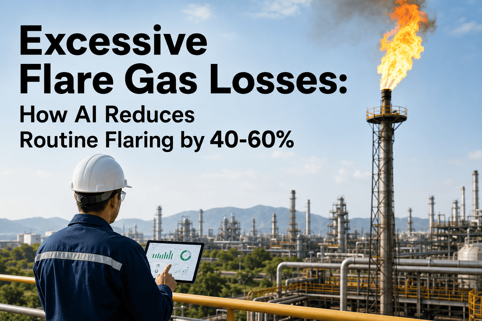
Excessive Flare Gas Losses — How AI Reduces Routine Flaring by 40% to 60%
AI-driven flare monitoring predicts relief valve lifting, optimizes compressor staging in real time, and automatically routes recoverable gas to fuel gas networks or NGL recovery instead of burning it at the flare tip.
The Anatomy of Routine Flaring — Why Gas Reaches the Flare Tip Without an Emergency
Emergency flaring is designed to protect plant equipment when pressure exceeds the maximum allowable working pressure of vessels and piping. Relief valves open, gas is routed to the flare header, and it is burned safely at the flare tip. This process is rare, necessary, and not the primary target of flare gas reduction efforts. Routine flaring, by contrast, occurs when gas is sent to the flare not because of an emergency, but because the refinery lacks the real-time control logic and predictive capability to route that gas to a productive use. A process unit transitioning between grades, a compressor operating slightly below its surge point, or a fuel gas header pressure that is temporarily satisfied can all result in gas being vented to the flare system even though there is technically capacity in the recovery network to absorb it.
The traditional refinery control architecture treats the flare system as a dead-end disposal route. The DCS controls individual process units to maintain their local targets, and any gas that cannot be contained within those local targets overflows into the flare header. There is no centralized optimization layer that looks across the entire refinery network to ask whether the gas heading for the flare could be absorbed by increasing the load on a flare gas recovery compressor, adjusting the setpoint on a fuel gas header, or redirecting a stream to an NGL recovery unit. The gas simply flows to the flare tip by default because no control system is actively managing the alternative routing. AI changes this by treating the flare header not as a disposal route, but as a managed process variable that should be minimized through proactive coordination of every available recovery pathway in the refinery.
Four Operational Drivers That Account for Most Routine Flaring Volume
Routine flaring is not a single problem with a single cause. It is the cumulative result of several operational dynamics that individually seem minor but together account for the vast majority of gas sent to the flare during normal refinery operations. Understanding which driver is dominant on a specific flare network is the first step toward designing an AI optimization strategy that targets the highest-value recovery opportunities. The relative contribution of each driver varies by refinery configuration, but the four categories below are consistently responsible for 80% to 90% of routine flare volume across the industry.
A minor temperature or pressure excursion in one unit, such as a distillation column flooding or a reactor temperature spike, causes the unit's pressure control system to vent gas to the flare to protect equipment. Because traditional control systems react to upsets after they occur, there is no opportunity to pre-emptively route the gas elsewhere. The gas is already in the flare header before the operator is aware of the magnitude of the upset. AI addresses this by detecting the early indicators of process instability—such as subtle changes in column differential pressure, heat exchanger approach temperatures, or feed composition—and predicting the upset before it triggers a pressure relief event. This prediction gives the flare gas recovery system time to spool up compressors and adjust routing before the gas arrives.
Flare gas recovery compressors are typically sized for a design capacity that represents the average expected flare gas flow, not the peak flow. During periods of high flare gas generation, the compressors reach their maximum flow capacity or approach their surge line, and any gas beyond what the compressors can handle is flared. In many refineries, compressors are operated conservatively with a wide margin to surge to avoid trip events, which means they are intentionally running below their actual recovery capacity. AI optimization continuously calculates the proximity of each compressor to its surge line and adjusts anti-surge valve positions and speed setpoints to maximize recovery flow while maintaining a safe margin, recovering gas that would otherwise be flared due to conservative manual operating margins.
The refinery fuel gas header is the primary destination for recovered flare gas, but it has a finite capacity to absorb additional volume without exceeding its pressure limits. If the fuel gas header is at its maximum allowable pressure, the flare gas recovery compressors have nowhere to discharge the gas, and it must be flared regardless of compressor capacity. This often happens during periods when multiple process units are simultaneously generating excess gas. AI coordinates the fuel gas header pressure with the flare gas recovery system by predicting header pressure trends and preemptively reducing other fuel gas supply sources—such as natural gas makeup or refinery gas from other units—to create headroom in the header before the flare gas arrives.
Not all routine flaring comes from dynamic process events. A significant portion comes from continuous leakage through blowdown valves, vent valves, and relief valves that do not seat properly. These leaks are often small individually—a few hundred kilograms per hour per valve—but they are continuous, and a large refinery may have dozens of leaking valves contributing to a substantial cumulative flare flow. AI monitoring detects these leaks by correlating flare header flow with process unit operating states. If the flare header flow remains elevated even when all process units are stable and no upsets are occurring, the platform flags the continuous flow as a likely leak and identifies which section of the flare network the flow is coming from based on pressure and temperature profiles along the header.
What Routine Flaring Actually Costs a Mid-Size Refinery Per Year
The financial impact of routine flaring extends beyond the calorific value of the burned gas. When gas is flared, the refinery loses not only the fuel value but also the potential liquid products that could have been extracted if the gas had been routed to an NGL recovery unit. Additionally, flaring generates CO2 emissions that may carry a direct carbon cost under emissions trading systems or carbon taxes. The economic profile below represents a typical 250,000 barrel-per-day refinery with moderate flare gas recovery infrastructure but significant room for AI-driven optimization.
Calculated from the volume of routine flaring multiplied by the equivalent fuel gas energy value. This represents the cost of purchasing natural gas or alternative fuel to replace the gas that was burned at the flare tip instead of being used as refinery fuel.
Flare gas contains recoverable propane, butane, and heavier hydrocarbons that have a higher per-unit value than fuel gas. When this gas is flared, these liquid products are destroyed. AI routing to the NGL recovery unit captures this premium value stream.
Based on a carbon price of $50 per ton and the CO2 generated by burning the routine flare volume. As carbon prices increase in major refining markets, this cost component is becoming a significant driver for flare reduction investment beyond the fuel savings.
Stop Treating the Flare Tip as Your Default Gas Disposal Route
See how AI flare gas analytics predict upsets, optimize compressor loading, and route recoverable gas to fuel gas and NGL recovery before it reaches the flare header.
Four Optimization Layers That Reduce Routine Flaring Without Compromising Safety
AI flare gas reduction does not interfere with the safety function of the relief valve network. Relief valves remain purely mechanical devices that open at their set pressure regardless of what the AI system is doing. The AI operates in the space below the relief valve setpoint, managing the control valves, compressor speeds, and routing decisions that determine whether gas reaches the relief valve in the first place. By keeping the flare header pressure below the relief valve setpoints through proactive recovery, the AI ensures that the safety system is never called upon to handle gas that could have been recovered.
The platform monitors hundreds of process variables across the refinery—temperatures, pressures, flows, levels, and compositions—looking for the early pattern signatures that historically precede a process upset severe enough to cause flaring. When a pattern is detected, the system generates an early warning, typically 5 to 15 minutes before the upset would trigger a relief valve, and automatically initiates flare gas recovery preparations such as starting standby compressors and opening routing valves.
Instead of operating compressors with a fixed conservative margin to surge, the AI continuously calculates the real-time surge boundary based on gas composition, suction temperature, and speed. It then positions the anti-surge recycle valve at the minimum safe opening and adjusts compressor speed to maximize throughput. This typically recovers 10% to 20% more flow from the same compressor hardware by eliminating the unnecessary safety margin that manual operation requires.
The platform treats the fuel gas header as a shared resource that must be actively managed to create reception capacity for flare gas. When a flare gas surge is predicted, the AI preemptively reduces natural gas makeup flow to the fuel gas header, allowing the header pressure to drop and creating room for the incoming flare gas. This coordination requires a refinery-wide view that individual unit control loops cannot provide.
When flare gas contains significant quantities of C3+ hydrocarbons, routing it to the fuel gas header destroys the liquid product value. The AI analyzes the real-time composition of the flare gas—using online gas chromatograph data or inferred composition models—and routes high-BTU, liquids-rich gas to the NGL recovery unit when it has available capacity, maximizing the economic value of the recovered gas rather than simply using it as fuel.
The AI Routing Decision — How the Platform Decides Where Flare Gas Should Go
When gas enters the flare header, the AI platform must make a rapid, multi-variable decision about where to route it. This decision is not based on a simple priority list but on a real-time optimization that considers the economic value of each routing option, the available capacity in each destination, the composition of the gas, and the current state of the downstream equipment. The decision matrix below illustrates how the platform evaluates the three primary routing options for a given volume of flare gas.
Selected when flare gas composition analysis indicates high C3+ content, the NGL recovery unit has available capacity, and the incremental liquid product revenue exceeds the fuel gas value by a sufficient margin to justify the routing change. The AI monitors NGL recovery unit inlet conditions and adjusts the flare gas routing valve to send liquids-rich gas to this destination, capturing the premium product value that would be lost if the gas were burned as fuel or flared.
Selected when the NGL recovery unit is at capacity, the gas composition is predominantly methane and ethane with low liquids content, and the fuel gas header has available pressure capacity. The AI coordinates with the fuel gas pressure controller to ensure that adding flare gas to the header does not cause overpressure, simultaneously reducing natural gas makeup to maintain the header pressure setpoint and avoid flaring the gas.
Selected only when both the NGL recovery unit and the fuel gas header are at maximum capacity, or when the flare gas volume exceeds the combined capacity of all recovery pathways. Even in this scenario, the AI optimizes the flaring by ensuring the flare pilot is lit, the assist gas is properly proportioned for smokeless combustion, and the flare header pressure is maintained within safe limits to prevent backpressure effects on the relief valves.
Measured Flare Reduction Results — Before and After AI Optimization
The following table summarizes typical performance improvements measured on refinery flare systems after 90 days of AI-driven optimization. The baseline represents the same flare network operating with conventional DCS control and manual compressor management. The post-AI values represent the network with the AI platform actively managing upset prediction, compressor loading, fuel gas coordination, and NGL routing. The 40% to 60% reduction range referenced in industry analyses is achievable when all four optimization layers are fully commissioned and the refinery has existing recovery infrastructure that is being underutilized.
| Performance Metric | Before AI Optimization | After AI Optimization |
|---|---|---|
| Annual routine flare volume | 12,000 tonnes per year | 5,400 tonnes per year (55% reduction) |
| Flare gas recovery compressor utilization | 65% of available capacity | 92% of available capacity |
| Time fuel gas header at max pressure | 18% of operating hours | 4% of operating hours |
| Upset-related flaring events per month | 14 events | 5 events |
| NGL recovery unit feed from flare gas | 8% of total feed | 22% of total feed |
| CO2 emissions from routine flaring | 35,000 tonnes per year | 15,750 tonnes per year |
The increase in compressor utilization from 65% to 92% is one of the most telling metrics in this comparison. It demonstrates that the recovery infrastructure was not the bottleneck— the control logic and operating practices were. The compressors had the physical capacity to recover significantly more gas, but the conservative manual operating margins and the lack of predictive coordination with the fuel gas header prevented that capacity from being used. AI optimization removes these operational bottlenecks without requiring any capital investment in new compressor hardware, delivering the majority of the flare reduction through better use of existing equipment.
Questions Refinery Engineers Ask About AI Flare Gas Reduction
Stop Burning $5.8 Billion a Year — Route Recoverable Gas to Fuel Gas and NGL Instead of the Flare Tip
AI-driven flare gas optimization that predicts upsets, maximizes compressor recovery capacity, and routes liquids-rich gas to NGL recovery — reducing routine flaring by 40% to 60% using your existing recovery infrastructure.