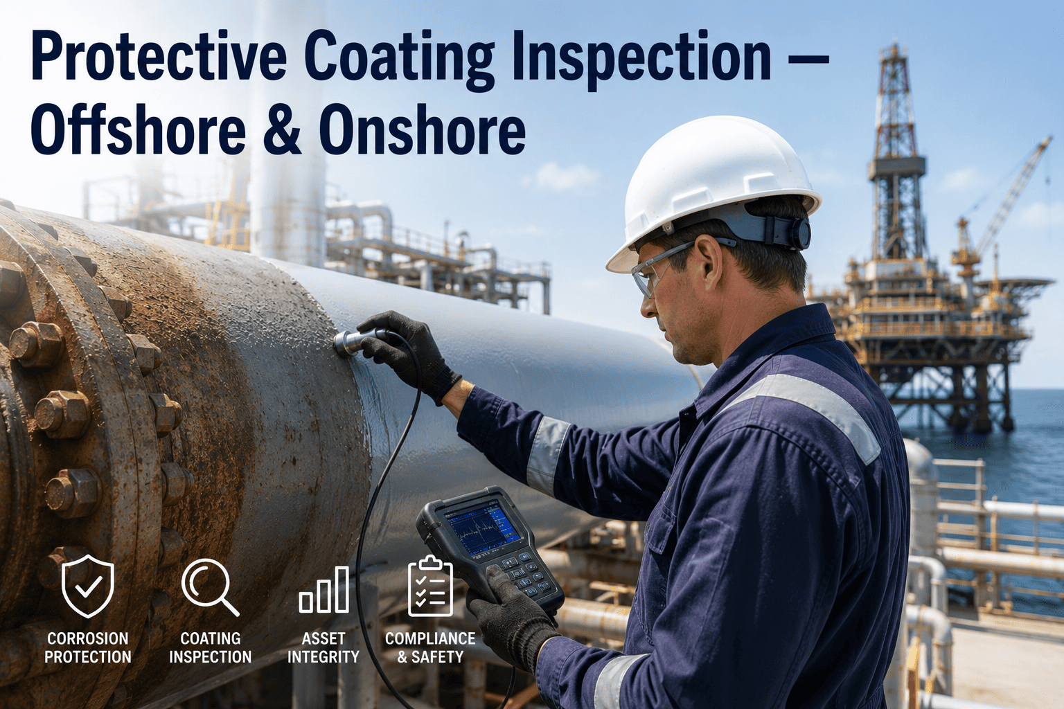
Protective coatings are the primary defense between oil and gas infrastructure and the corrosive environments that continuously attack steel surfaces — yet the majority of premature coating failures trace directly back to inadequate inspection during surface preparation and application rather than coating product deficiency. Offshore platforms face salt spray immersion, UV degradation, and thermal cycling that accelerate coating breakdown at rates four to six times faster than onshore facilities. A structured coating inspection program that verifies surface preparation quality, monitors application parameters in real time, and conducts systematic in-service condition assessments is the only approach that delivers the full design life of a coating system. To see how digital inspection workflows improve coating quality outcomes, book a demo with our team.
COATING INSPECTION · OIL AND GAS · EQUIPMENT RELIABILITY
Digitize Your Protective Coating Inspection Workflows for Offshore and Onshore Assets
iFactory's equipment reliability platform streamlines coating inspection from surface preparation verification through DFT measurement, adhesion testing, and failure analysis with complete audit traceability across every asset.
Industry Impact
The Real Cost of Coating Failure in Oil and Gas Operations
Corrosion-related asset degradation costs the global oil and gas industry over one trillion dollars annually, and the single largest controllable factor in that figure is coating system performance. When protective coatings fail prematurely, the consequences cascade far beyond the visible rust spot — structural integrity diminishes, wall thickness loss accelerates, environmental leak risk increases, and regulatory non-compliance triggers mandatory shutdowns. The data below quantifies the scale of this problem and the specific leverage points where inspection quality directly determines coating system outcomes.
$1.37T
Annual global cost of corrosion across oil and gas operations, with coating failure as the largest single contributing factor per NACE International estimates
60-85%
Of all premature coating failures attributed directly to inadequate surface preparation — not coating material deficiency or application technique alone
3-5x
Cost multiplier for offshore coating repair compared to original application, driven by logistics, weather windows, scaffolding, and access constraints
40-60%
Of expected coating service life lost when surface preparation does not meet the specified cleanliness and profile requirements before application begins
Surface Preparation
Surface Preparation Verification — The Inspection Checklist That Determines Coating Success
Surface preparation accounts for the largest share of coating system performance variance, yet it remains the most frequently shortcut phase in field application. Every coating system specification defines measurable acceptance criteria for surface condition before any coating material is applied. The following six verification checkpoints represent the minimum inspection requirements that must be satisfied and documented before coating application can proceed. Skipping any single checkpoint introduces a failure risk that no amount of coating thickness or topcoat quality can compensate for.
01
Solvent Cleaning Verification
Confirm all visible oil, grease, weld spatter, and soluble contaminants have been removed from the steel surface before abrasive blasting begins. Solvent cleaning is a prerequisite step — blasting over contaminated surfaces drives contaminants into the surface profile and guarantees premature coating adhesion failure.
Required Before Blast
02
Abrasive Blast Profile Measurement
Measure anchor profile depth at a minimum of five locations per inspected area using replica tape or surface profile comparators. Profile depth must fall within the coating manufacturer specified range — typically 50 to 100 microns for most epoxy systems used in oil and gas service.
50-100 Microns Typical
03
Surface Cleanliness Assessment
Visually assess the blasted surface against SSPC-SP 10/NACE No. 2 near-white metal standards or the applicable specification grade. The surface must be free of visible oil, grease, dust, rust, mill scale, paint, and other foreign matter as defined by the specified cleanliness level.
Near-White Metal Min
04
Soluble Salt Contamination Testing
Conduct conductivity or chloride ion extraction testing to quantify soluble salt levels on the blasted surface. Chloride contamination above 50 mg per square meter is widely recognized as a threshold above which osmotic blistering risk increases significantly — many offshore specifications require levels below 20 mg per square meter.
Below 50 mg/m2 Critical
05
Dew Point and Surface Temperature Verification
Measure ambient temperature, relative humidity, and steel surface temperature. Surface temperature must be at least 3 degrees Celsius above the dew point throughout the coating application and curing period. Condensation on a freshly blasted or coated surface causes immediate adhesion compromise and flash rust.
Min 3C Above Dew Point
06
Blast Profile Angularity and Uniformity Assessment
Verify that the abrasive blast media produces the required angular profile geometry — not just depth. Rounded profiles from worn or incorrect blast media provide reduced mechanical anchoring compared to angular profiles from correctly graded garnet, copper slag, or steel grit at proper velocity and angle.
Angular Profile Required
Application Parameters
Critical Coating Application Parameters — What Inspectors Must Measure and Verify
During coating application, the inspector's role shifts from preparation verification to real-time parameter monitoring. Each coating system specification defines acceptable ranges for application conditions, and every measurement outside those ranges must be documented and addressed before application continues. The following five parameters represent the most frequently monitored and most consequential application inspection points across offshore and onshore coating projects in oil and gas service.
Dry Film Thickness (DFT)
Acceptable Range: 200-400 microns per coat
Method: Magnetic or eddy current gauge per SSPC-PA 2
Critical: Below minimum triggers re-coat; above maximum may cause curing defects
Wet Film Thickness (WFT)
Acceptable Range: Calculated from DFT target and volume solids percentage
Method: Wet film thickness gauge comb per ASTM D4417
Critical: Real-time indicator — allows correction before coating cures
Surface Profile Depth
Acceptable Range: 50-100 microns for most epoxy systems
Method: Replica tape per ASTM D4417 Method C or comparator per Method B
Critical: Below minimum = inadequate anchor; above maximum = profile peaks exceed coating coverage
Ambient Temperature
Acceptable Range: 5-35 degrees Celsius for most coating systems
Method: Calibrated digital thermometer or surface temperature probe
Critical: Below minimum slows cure; above minimum causes flash-off defects and reduced pot life
Dew Point Margin
Acceptable Range: Minimum 3 degrees Celsius above calculated dew point
Method: Sling psychrometer or digital dew point meter per ASTM E337
Critical: Below 3 degrees margin = immediate stop — condensation risk on coated surface
Environment Comparison
Offshore vs Onshore Coating Inspection — How Environment Changes Everything
The fundamental inspection procedures defined by API, NACE, and SSPC standards apply to both offshore and onshore coating work, but the operational context in which those procedures are executed differs dramatically. Offshore coating inspection must account for environmental exposure that accelerates coating degradation, access constraints that limit inspection frequency, and logistical costs that make every repair decision significantly more consequential than an equivalent onshore finding. The following comparison captures the practical differences that inspectors and reliability engineers must account for when planning and executing coating inspection programs across different operating environments.
Offshore vs Onshore Protective Coating Inspection Comparison
Failure Analysis
Coating Failure Mode Identification — Symptom, Root Cause, and Corrective Action
When coating inspections reveal degradation, accurate failure mode identification is the prerequisite for selecting the correct corrective action. Treating a blistering failure as a simple surface defect without addressing the underlying soluble salt contamination will result in repeated failure after repair. The following six failure modes represent the most frequently encountered coating degradation types in oil and gas service, each with distinct visual symptoms, root causes that inspection should identify, and corrective actions that address the actual failure mechanism rather than just the visible symptom.
Blistering
Visual Symptom
Dome-shaped raised areas on coating surface, ranging from small pinhead blisters to large areas of coating elevation. May contain liquid or gas under pressure when ruptured.
Root Cause
Soluble salt contamination on substrate creating osmotic pressure differential, entrapped solvents from improper cure, or cathodic disbondment in CP-integrated systems.
Corrective Action
Remove blistered coating, re-blast affected area, conduct soluble salt testing, and reapply coating only after contamination source is identified and eliminated.
Undercutting and Creep
Visual Symptom
Loss of adhesion spreading outward from damaged areas, edges, or welds. Coating lifts away from substrate in a widening pattern, often with visible corrosion product beneath the disbonded coating.
Root Cause
Inadequate edge preparation at damaged areas, poor adhesion at welds due to incorrect profile, or anodic undercutting where the coating acts as a cathode relative to exposed steel at defects.
Corrective Action
Feather-edge the coating boundary at least 50mm beyond visible disbondment, re-blast to specified profile, and apply tie-coat and topcoat with proper overlap beyond the repaired area.
Chalking
Visual Symptom
Powdery white or colored residue on the coating surface that transfers to fingers when wiped. Surface appears faded and loses gloss progressively. Does not immediately expose substrate but indicates binder degradation.
Root Cause
UV radiation breaking down the resin binder at the coating surface, particularly in alkyd and some epoxy topcoats not formulated with UV-resistant pigments and resins for the exposure environment.
Corrective Action
Light abrasive sweep blast or water jet to remove chalk layer, apply UV-resistant intermediate coat if remaining film is sound, or full recoat with aliphatic polyurethane topcoat.
Cracking and Crazing
Visual Symptom
Linear fractures in the coating surface — crazing appears as a fine network of shallow cracks while cracking shows deeper, wider fractures that may extend to the substrate. Pattern may be irregular or follow stress paths.
Root Cause
Thermal cycling stress exceeding coating flexibility, over-thickness application creating internal stress, incompatibility between coating layers, or substrate movement from structural loading and vibration.
Corrective Action
Remove cracked coating to sound substrate, verify DFT did not exceed maximum specification, assess whether coating system is appropriate for thermal cycling conditions, and reapply with correct thickness control.
Flaking and Delamination
Visual Symptom
Coating separating from substrate or from underlying coats in flat pieces or flakes. Exposed substrate surface is often visibly corroded. Delamination may occur at the primer-substrate interface or between coating layers.
Root Cause
Contaminated blast surface, coating applied over flash rust, exceeded maximum recoat window creating inter-coat adhesion failure, or improper surface profile that provides insufficient mechanical anchor.
Corrective Action
Full removal of disbonded coating, re-blast to restore specified profile and cleanliness, verify environmental conditions are within specification, and reapply complete coating system with strict recoat window compliance.
Rusting Through Coating
Visual Symptom
Red-brown rust stains or spots visible on the coating surface, indicating that corrosion has initiated at the substrate and corrosion products have migrated through the coating film to the surface.
Root Cause
Coating porosity allowing moisture and oxygen penetration, mechanical damage exposing substrate, coating thickness below minimum specification at the affected location, or coating degradation from chemical exposure.
Corrective Action
Assess extent of rusting and substrate loss through thickness measurement, spot blast to remove rust and degraded coating, feather edges, and recoat with verified DFT meeting minimum specification at repair area.
Inspection Methods Matrix
Coating Inspection Methods — When to Apply Each Technique Across the Coating Lifecycle
Effective coating inspection requires selecting the right measurement technique for each stage of the coating lifecycle. Applying a method at the wrong stage produces meaningless data, while failing to apply a required method at the correct stage creates an undocumented quality gap that can result in premature failure with no inspection record to explain why. The following matrix maps each primary inspection method to the lifecycle stages where it provides critical quality assurance value. For a guided walkthrough of how iFactory structures these inspections digitally, book a demo with our engineering team.
Inspection Method
Surface Preparation
Coating Application
Curing and Dry
In-Service
Primary Application
Secondary Application
Not Typically Applied
Standards Reference
Governing Standards for Protective Coating Inspection in Oil and Gas
Protective coating inspection in oil and gas is governed by a framework of interrelated standards from NACE International, SSPC, ASTM International, and ISO that define everything from surface preparation acceptance criteria to measurement procedures and documentation requirements. Inspectors must be familiar with the specific standards referenced in each coating specification, as the acceptance criteria and measurement methods can vary significantly between standards that appear to cover the same subject. The following reference cards summarize the primary standards most frequently encountered in offshore and onshore coating inspection programs.
NACE No. 2 / SSPC-SP 10
Near-White Metal Blast Cleaning
Defines the visual standard for near-white metal blast cleanliness. The most commonly specified surface preparation level for protective coatings in oil and gas service, particularly for offshore and immersion environments where maximum coating performance is required.
SSPC-PA 2
Dry Film Thickness Measurement
Establishes procedures for measuring dry film thickness on ferrous and non-ferrous substrates including gauge calibration requirements, spot measurement definitions, and statistical acceptance criteria for batch and area measurements.
ASTM D4541
Pull-Off Adhesion Testing
Specifies the test method for measuring the pull-off strength of coating systems using portable adhesion testers. Defines dollie preparation, glue application, pull rate, and failure mode classification that determines whether adhesion values are acceptable.
NACE SP0287
Holiday Detection on Coatings
Covers the use of low-voltage and high-voltage holiday detection equipment to find discontinuities in coating films that expose the substrate. Defines voltage selection based on coating thickness and the procedures for systematic survey of coated surfaces.
ISO 12944
Corrosion Protection of Steel Structures by Paint Systems
The overarching international standard that defines corrosivity categories, coating system durability ranges, surface preparation requirements, and design considerations for protective paint systems on structural steel across all environments.
ASTM D4417
Surface Profile Measurement Methods
Defines three methods for measuring the surface profile of blast-cleaned steel: Method A uses surface profile comparators, Method B uses replica tape, and Method C uses stylus instruments. Each method has specific accuracy characteristics and field applicability.
Frequently Asked Questions
Protective Coating Inspection — Frequently Asked Questions
What is the difference between wet film thickness and dry film thickness measurement in coating inspection?
Wet film thickness is measured during coating application using a comb gauge inserted into the freshly applied wet film, providing an immediate indication of whether the applied thickness will produce the required dry film thickness after solvent evaporation. Dry film thickness is measured after the coating has cured using a magnetic or eddy current gauge and represents the actual protective film thickness that determines corrosion protection performance. WFT is a real-time process control tool that allows the applicator to adjust technique before the coating cures, while DFT is the quality acceptance measurement that determines whether the coated area meets the specification. Both measurements are required by SSPC-PA 2 for a complete inspection record, and the relationship between them depends on the coating's volume solids percentage. To see how iFactory automates both measurements in a single digital workflow,
book a demo with our team.
How often should protective coatings be inspected on offshore oil and gas platforms?
Inspection frequency depends on the structural zone and corrosion exposure severity. Splash zone coatings — the most aggressively degraded area on any offshore platform — typically require quarterly visual inspection and annual detailed condition assessment including DFT measurement and adhesion testing. Atmospheric zone coatings above the splash zone generally require semi-annual visual inspection and biennial detailed assessment. Submerged zone coatings, where cathodic protection provides the primary corrosion defense, are inspected annually with coating condition assessed during CP survey dives or ROV inspections. The inspection program should be defined in the asset integrity management plan and adjusted based on actual degradation rates observed over successive inspection cycles. For support establishing inspection frequencies aligned with your asset integrity requirements,
contact support.
What is holiday detection and when is it required during coating inspection?
Holiday detection is a non-destructive testing method that identifies pinholes, cracks, and other discontinuities in a coating film that expose the underlying substrate to the corrosive environment. Low-voltage wet sponge holiday detection is used for thin-film coatings below 500 microns, while high-voltage spark testing is used for thicker coatings and immersion service linings where the voltage is calculated based on coating thickness per NACE SP0287. Holiday detection is required as a final acceptance test for all coatings in immersion service, for tank linings, for pipeline coatings, and for any offshore coating system where a single through-film defect could initiate rapid localized corrosion that compromises structural integrity. The test must be performed after the coating has fully cured and before the structure is returned to service. To explore how digital holiday detection records integrate with broader coating management workflows,
book a demo.
How does surface preparation quality affect long-term coating performance in oil and gas service?
Surface preparation quality is the single most influential variable in determining coating service life — industry failure analysis consistently attributes 60 to 85 percent of premature coating failures to inadequate surface preparation rather than coating material deficiency. The blast profile provides mechanical anchoring that the coating bonds to through physical interlocking, and the cleanliness level determines whether contaminants are present at the coating-substrate interface that will initiate adhesion failure, osmotic blistering, or underfilm corrosion. A surface prepared to SSPC-SP 10 near-white metal with the correct anchor profile depth and verified soluble salt levels below the specified threshold will routinely deliver the full design life of the coating system, while the same coating applied over a surface with marginal cleanliness or incorrect profile may fail in 40 to 60 percent less time. For support implementing surface preparation verification procedures,
contact support.
What qualifications should a protective coating inspector hold for oil and gas projects?
Coating inspectors working on oil and gas projects should hold NACE Certified Coating Inspector Level 2 certification as the baseline qualification for independent inspection responsibility, with NACE CIP Level 3 required for senior inspection roles and complex project oversight. SSPC CCI certification provides an equivalent qualification framework recognized alongside NACE credentials. For offshore work, additional qualifications may include rope access certification (IRATA or equivalent), confined space entry training, and specific operator-mandated safety certifications. Inspectors must also demonstrate working knowledge of the specific standards referenced in the coating specification for each project, including the applicable NACE, SSPC, ASTM, and ISO standards that define acceptance criteria and measurement procedures. To see how iFactory tracks inspector qualifications and maps them to project requirements,
book a demo.
COATING INSPECTION · EQUIPMENT RELIABILITY · OIL AND GAS
Transform Coating Inspection from Manual Checklists to Digital Quality Assurance
iFactory's platform digitizes surface preparation verification, application parameter tracking, DFT and adhesion testing records, and failure analysis workflows with full traceability from inspection to corrective action across every offshore and onshore asset in your portfolio.


-for-offshore-environmental-monitoring.png)