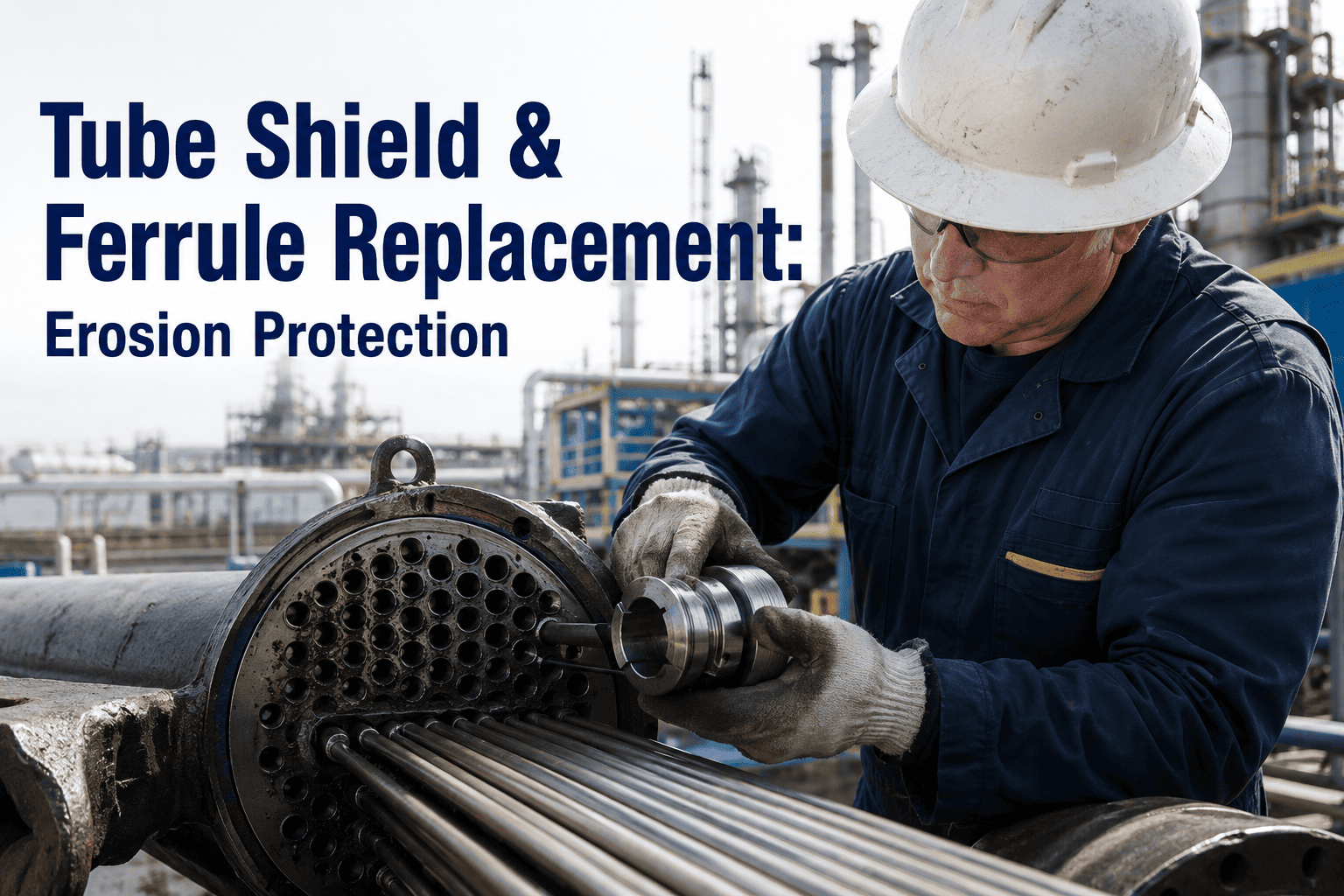
Boiler tube erosion is the single most predictable cause of forced outages in coal-fired and biomass power plants, yet most maintenance teams still react to it after the tube wall has already thinned past the minimum allowable thickness. Soot blower lanes, fly ash impact zones, and flue gas turning sections chew through carbon steel at rates that can exceed 0.5 millimeters per thousand operating hours. The protection options available today — welded tube shields, ceramic ferrules, thermal spray coatings, and weld overlays — each carry distinct trade-offs in cost, service life, and installation complexity. Understanding which method fits which zone and how to track replacement intervals across hundreds of tubes is what separates plants that plan outages from plants that get shut down by them. To see how iFactory structures tube protection tracking for your boiler, book a 30-minute demo.
Tube Shield and Ferrule Replacement: The Complete Erosion Protection Playbook for Industrial Boilers
A field-validated guide to selecting, installing, and tracking tube shields, ferrules, thermal spray coatings, and weld overlays across every erosion-vulnerable zone in your boiler.
Four Erosion Mechanisms That Destroy Boiler Tubes
Not all boiler tube erosion is the same. The particle velocity, impact angle, temperature, and material hardness at each location create fundamentally different wear patterns. Selecting the right protection method starts with correctly identifying which mechanism is active at the target zone. The four mechanisms below account for over 95 percent of all tube-wall thinning events in utility and industrial boilers across all fuel types and boiler configurations.
Solid Particle Impingement
Fly ash particles entrained in flue gas strike tube surfaces at high velocity, typically at angles between 15 and 45 degrees. The kinetic energy of each particle microscopically deforms and removes surface material. Erosion rate scales with the square of particle velocity — a 20 percent increase in gas velocity roughly doubles the wear rate. This is the dominant mechanism in superheater and reheater banks where flue gas velocities exceed 15 meters per second and ash loading is at its peak before any settling occurs.
Soot Blower Erosion
Rotary and retractable soot blowers direct high-pressure steam or air at tube surfaces to remove ash deposits. When the lance tube is misaligned, the nozzle rotates past its design arc, or the blow pressure exceeds specification, the cleaning medium becomes an erosion tool. Soot blower erosion typically creates a localized gouge pattern 50 to 150 millimeters wide centered on the blow path. It is the single most common cause of tube leaks in coal-fired units and accounts for the majority of shield replacements performed during scheduled outages.
Falling Slag Erosion
In the furnace and lower convection pass, molten or semi-molten slag detaches from waterwall surfaces and falls onto tubes below. The combination of thermal shock and mechanical impact creates a characteristic pitting and gouging pattern on the tube crown. Falling slag erosion is particularly aggressive in units burning low-melting-point coals or co-firing biomass, where slag viscosity is reduced and shedding frequency increases. The irregular shape of slag chunks also means impact energy is concentrated at sharp edges, creating deeper local damage than spherical fly ash particles at equivalent mass.
Fluidized Bed Erosion
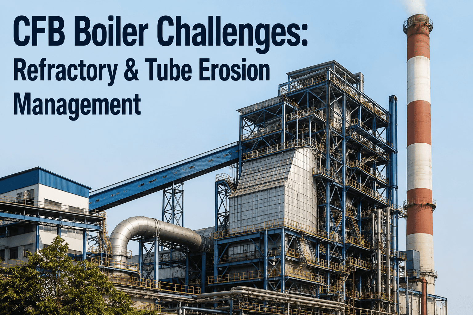
In circulating fluidized bed boilers, the bed material — typically silica sand or limestone — circulates at high density through the combustion chamber and convective pass. Tube surfaces in the bed zone experience continuous low-angle abrasion from millions of particle contacts per second. Erosion rates in CFB units can be two to three times higher than in pulverized coal units at equivalent gas velocities, making protection systems essential from day one of operation. The high particle density also means that erosion is less localized than in PC units — the entire tube circumference in the bed zone is under continuous attack rather than a single windward face.
High-Risk Zones: Where Every Boiler Needs Protection
Boiler tube erosion is not uniformly distributed. Inspection data from over 200 utility and industrial units consistently shows that 70 to 80 percent of all tube-wall loss occurs in a small number of predictable locations. Targeting these zones with the right protection method delivers disproportionate impact on outage frequency and tube replacement spend. The six zones below represent the highest-priority targets for any tube protection program and should be the first areas evaluated during any boiler integrity assessment.
Soot Blower Lane Tubes
Tubes directly in the path of soot blower steam jets experience the most aggressive localized erosion in the boiler. Shield coverage here is non-negotiable — every soot blower lane should have shields on both the windward and leeward tube rows within the blow arc. Shield length must extend at least 100 millimeters beyond the maximum documented blow pattern on each side to account for nozzle drift and steam deflection.
Superheater Leading Row
The first row of superheater tubes takes the full impact of flue gas carrying the highest ash loading and velocity. These tubes typically thin 30 to 50 percent faster than tubes in the interior banks. Full-circumference shields or thermal spray coating on the leading half of the tube are the standard approaches, with material selection driven by tube metal temperature at that location.
Economizer Inlet Rows
Economizer inlet tubes face fly ash impingement at gas temperatures where ash particles are still hard and brittle, maximizing their erosive potential. The lower metal temperature at the economizer also means carbon steel shields are often sufficient, making this one of the most cost-effective zones to protect. Shields here typically last 8 to 12 years before replacement is required.
Flue Gas Turning Sections
Where flue gas changes direction — at the furnace exit, the nose arch, and the economizer turnaround — centrifugal force concentrates ash particles against the outer wall tubes. The impact angle shifts toward 90 degrees in these sections, changing the wear pattern from a smooth crescent to a deep, localized pit. Shields in turning sections need to account for multi-directional particle flow.
Waterwall Lower Section
The lower waterwall zone in coal-fired boilers faces a combination of falling slag impact, low-velocity abrasion from bed ash, and occasional thermal shock from slag shedding. Protection here is complicated by the need to maintain heat transfer — full-coverage shields are rarely acceptable. Instead, localized shields at known slag-shed points and refractory-lined zones provide targeted protection without degrading boiler efficiency.
Tube Entry Points and Ferrule Locations
Where tubes enter headers, drum walls, or refractory penetrations, the geometry change creates turbulence and localized erosion at the tube end. Ceramic ferrules installed at these transition points protect the tube end from the erosion vortex that forms at the entry. Ferrule replacement is typically driven by thermal cycling fatigue rather than pure erosion, making material selection a balance between erosion resistance and thermal shock tolerance.
Protection Methods Compared: Which Tool for Which Job
The boiler tube protection market offers four primary methods, each with distinct advantages, limitations, and cost profiles. The table below provides a field-validated comparison to help maintenance engineers and plant managers make informed decisions for each zone in their boiler. No single method is universally best — the right choice depends on erosion mechanism, tube temperature, accessibility, and budget cycle.
| Parameter | Welded Tube Shield | Ceramic Ferrule | Thermal Spray Coating | Weld Overlay |
|---|---|---|---|---|
| Erosion Mechanism | Impingement, soot blower | Turbulence at entry points | All mechanisms | All mechanisms |
| Max Service Temperature | 750C (SS 309/310) | 1,400C (silicon carbide) | 800C (NiCr/Cr3C2) | 900C (Inconel 625) |
| Typical Service Life | 3-8 years | 5-10 years | 4-10 years | 10-15 years |
| Install Time per Tube | 10-20 minutes | 5-10 minutes | 2-5 minutes (HVOF) | 30-60 minutes |
| Heat Transfer Impact | Moderate (air gap) | Low (localized only) | Minimal (thin layer) | None (alloyed surface) |
| Material Cost per Tube | $15-80 | $8-35 | $25-120 | $80-250 |
| Removal Difficulty | Moderate (grind weld) | Easy (push out) | Difficult (mech. strip) | Very difficult |
| Inspection Visibility | Shield must be removed | Ferrule must be removed | Coating visible on UT | Same as base tube |
| Best Suited For | Soot blower lanes, leading rows | Header entries, penetrations | Large surface areas | Critical high-value tubes |
Tube Shield Engineering: Material Selection and Geometry
The performance of a tube shield is determined by three factors: the alloy composition, the shield geometry, and the attachment method. Getting any one of these wrong reduces service life by 40 to 60 percent and can create secondary problems like under-shield corrosion or heat transfer starvation. The following breakdown covers the decisions that matter most in field applications and the trade-offs that separate a well-engineered shield program from a costly trial-and-error approach.
Matching Alloy to Temperature and Corrosives
Carbon steel shields (AISI 1010/1020) are the most cost-effective option and perform well in economizer and low-temperature superheater zones where tube metal temperatures stay below 450 degrees Celsius. For higher temperature zones — reheater tubes, high-temperature superheater, and furnace exit areas — austenitic stainless steels like SS 304H, SS 309S, and SS 310S provide the necessary creep strength and oxidation resistance at temperatures up to 750 degrees Celsius. In units burning high-chlorine coals or biomass, Inconel 625 or 825 shields resist chlorine-induced corrosion that would rapidly degrade standard stainless grades. The material upgrade from carbon steel to SS 310 roughly triples the per-shield cost but can extend service life by four to five times in high-temperature zones — a trade-off that almost always pays for itself in reduced outage frequency and avoided tube replacements.
Half-Shell, Full-Shell, and Flat-Back Profiles
Half-shell shields cover approximately 180 degrees of the tube circumference and are the standard choice for soot blower lanes and leading rows where erosion arrives from a predictable direction. Full-shell shields provide 360-degree coverage and are used in turning sections and turbulent zones where particle impact angles vary. Flat-back shields are designed to sit flush against adjacent tubes in closely spaced banks, minimizing flow disruption. The inner diameter of the shield must be sized 1.5 to 3 millimeters larger than the tube outer diameter to allow for thermal expansion differential without binding. Shield wall thickness typically ranges from 2 to 4 millimeters — thicker shields last longer but increase the air gap and reduce heat transfer, requiring careful balance in high-duty zones where even a small efficiency loss compounds over thousands of operating hours.
Welded, Clamped, and Crimped Installation
Welded attachment is the most secure method and is mandatory in soot blower lanes where vibration and steam impulse could dislodge a clamp-on shield. Shield welding uses short fillet welds at each end, typically 10 to 15 millimeters in length, applied with GTAW or SMAW using a matching or over-alloyed filler. Clamped shields use spring-loaded or bolted band clamps that grip the tube without welding — these are preferred in economizer and waterwall applications where future shield removal for tube inspection is planned. Crimped shields are formed with a slight inward lip that snaps over the tube diameter; they are the fastest to install but the least secure and are limited to low-erosion, low-vibration zones. The attachment method directly affects inspection access: welded shields require grinding to remove, while clamped shields can be loosened and repositioned in minutes without heat input to the tube.
Ferrule Replacement: A Step-by-Step Field Protocol
Ceramic ferrules protect tube ends at header connections, refractory penetrations, and membrane wall openings from the turbulence-induced erosion vortex that forms at every geometry transition. Unlike tube shields, ferrules operate in a relatively narrow temperature band but face extreme thermal cycling stress. A proper replacement protocol ensures the new ferrule seats correctly, seals the gap, and survives the next operational cycle without cracking. The seven-step process below reflects field best practices refined across hundreds of outages in plants ranging from 50 MW industrial units to 800 MW utility boilers.
Tube End Condition Assessment
Before removing the existing ferrule, measure the tube end wall thickness using ultrasonic testing at four quadrants. Document the erosion pattern — if the tube end has thinned below 60 percent of nominal wall thickness, the tube must be stub-replaced before a new ferrule is installed. Installing a new ferrule over a critically thinned tube end masks the underlying problem and guarantees a repeat failure within the next operating cycle, potentially with more severe consequences if the tube end fails under pressure.
Existing Ferrule Extraction
Carefully remove the existing ferrule by tapping it axially with a non-metallic drift. Avoid prying laterally, which can crack the tube end or damage the header stub. Inspect the extracted ferrule for failure mode — circumferential cracks indicate thermal cycling fatigue, while erosion on the inner surface indicates the ferrule was undersized or the gap was too large. This forensic data informs material selection for the replacement and helps identify if the operating conditions have changed since the previous installation.
Tube End Preparation
Clean the tube end to bare metal using a wire brush or light grinding. Remove any weld spatter, slag, or corrosion products that would prevent the ferrule from seating fully. Verify the tube end is square — a chamfered or beveled tube end creates an uneven gap that accelerates ferrule wear on one side and allows gas bypass on the other. Measure the tube outer diameter at three points to confirm it falls within the ferrule specified tolerance range before proceeding to selection.
Ferrule Size Verification
Select the replacement ferrule with an inner diameter 1 to 2 millimeters larger than the measured tube outer diameter. This gap is critical — too tight and thermal expansion will crack the ferrule during startup, too loose and the erosion vortex will accelerate wear on the tube end behind the ferrule. For high-temperature applications above 600 degrees Celsius, use silicon carbide or alumina ferrules; for lower temperature zones, mullite or cordierite ceramics provide adequate performance at significantly lower material cost while maintaining sufficient erosion resistance.
Ferrule Installation and Seating
Slide the ferrule onto the tube end with a gentle axial push — never hammer a ceramic ferrule into position. The ferrule should seat fully against the shoulder or refractory face without any rocking or wobble. If the ferrule does not seat cleanly, do not force it — recheck the tube end for burrs or out-of-roundness. Apply a high-temperature ceramic sealant around the gap between the ferrule inner wall and the tube outer wall to prevent gas bypass and localized erosion behind the ferrule that would otherwise go undetected until the next inspection.
Gap Documentation and Mapping
Record the installed ferrule location, material grade, inner diameter, and measured gap at four quadrants in the tube protection database. This data is the foundation for predicting when the ferrule will need replacement — a ferrule with a 2 millimeter gap in a 540 degree Celsius service will typically reach end-of-life in 6 to 8 years, while the same ferrule with a 3.5 millimeter gap may fail in 3 years. Without this documentation, replacement intervals are guesses, and plants either replace too early and waste material or too late and risk tube end failure.
Post-Installation Verification
After all ferrules in the scope are installed, perform a visual walk-down of every replaced ferrule to confirm seating, sealant application, and absence of visible damage. For critical header connections, consider a borescope inspection of the gap to verify sealant coverage. Log the completion date, technician ID, and any deviations from the standard protocol in the maintenance record. This closeout step is the one most often skipped in the rush to close an outage scope, and it is the one most correlated with premature ferrule failures discovered on the next outage.
Stop Guessing Replacement Intervals — Track Every Shield and Ferrule With iFactory
iFactory maps every tube shield, ferrule, and coated section to your boiler tube layout, tracks installation dates and material grades, and calculates remaining service life based on your operating hours and measured erosion rates. No more spreadsheets. No more missed replacements. One platform, every tube, every outage.
Thermal Spray Coating vs Mechanical Shields: The Decision Matrix
Two of the most common protection approaches — thermal spray coatings and mechanical tube shields — serve overlapping but distinct use cases. The decision between them is not simply a cost comparison; it involves trade-offs in coverage area, installation logistics, inspection access, and long-term maintainability that have profound implications for outage planning and boiler performance over a 20 to 30 year operating life.
When Coating Is the Right Choice
Thermal spray coating — particularly HVOF (high-velocity oxy-fuel) and arc spray — applies a thin, dense layer of erosion-resistant material directly to the tube surface. The coating thickness is typically 0.3 to 0.8 millimeters, which means heat transfer impact is negligible. Coating is the clear winner when you need to protect large surface areas — an entire superheater bank, for example — where installing individual shields on every tube would be prohibitively labor-intensive. It is also the only practical option for tubes in tight banks where there is no physical access to clamp or weld a shield between adjacent tubes. The limitation is that coating cannot be visually inspected without specialized ultrasonic equipment, and repair of a localized coating failure requires abrasive blasting and re-spray of the affected area with surface preparation that may not be feasible during a short-duration outage. Coating also cannot compensate for a tube that has already thinned — it must be applied to a tube with adequate remaining wall thickness to provide structural benefit.
When Shields Are the Right Choice
Mechanical shields provide a sacrificial barrier between the erosion source and the tube wall. The shield absorbs the wear, and when it reaches end-of-life, it is replaced — leaving the original tube intact beneath. Shields are the right choice for localized high-erosion zones like soot blower lanes, where the erosion pattern is concentrated in a narrow band and a shield can be precisely sized to cover it. They are also preferred when the maintenance team needs to visually inspect the tube surface during outages — the shield is removed, the tube is inspected, and the shield is replaced or reinstalled in the same outage window. Shields are faster to install on a per-tube basis than coating, but the labor cost scales linearly with the number of tubes, making them less economical for full-bank protection of hundreds of tubes. The air gap between shield and tube reduces heat transfer by 5 to 15 percent in the shielded zone, which must be accounted for in boiler performance modeling and may affect steam temperature control in sensitive zones.
Unsure whether coating or shields fit your boiler geometry and operating profile? Book a 30-minute protection assessment — iFactory will map the recommendation to each zone in your unit.
Replacement Interval Planning: A Data-Driven Framework
The single biggest failure in tube protection programs is not choosing the wrong material — it is replacing protections on a calendar schedule instead of a condition-based schedule. A shield that lasts 8 years in one unit may fail in 3 years in another unit burning a different coal with different ash characteristics. The framework below provides a structured approach to setting and adjusting replacement intervals based on actual operating data rather than manufacturer claims or historical assumptions that may no longer be valid.
The foundation of any replacement interval calculation is the measured erosion rate on the protection itself. During each outage, measure the remaining thickness of representative shields or ferrules using ultrasonic testing or micrometer measurement. Calculate the annualized wear rate and divide the remaining usable thickness by that rate to estimate remaining life. This is the only reliable baseline — manufacturer life claims are based on standardized test conditions that rarely match your actual operating environment, fuel composition, and flue gas velocity profile.
Erosion only occurs when the boiler is operating and flue gas is flowing at velocity. A unit that runs at a 60 percent capacity factor accumulates erosion at roughly 60 percent the rate of a baseload unit, all else being equal. Replacement intervals should be expressed in operating hours, not calendar years, and should be adjusted each cycle based on actual hours logged since the previous replacement. A shield installed for a projected 8-year life at baseload operation will last over 13 years if the unit cycles to 60 percent capacity factor — replacing it at year 8 wastes material and labor budget that could be allocated to higher-priority scope items.
Changes in fuel source — particularly shifts in ash hardness measured by Mohs scale, silica content, and chlorine concentration — directly affect erosion rates in ways that are often underestimated. A plant that switches from a high-moisture sub-bituminous coal to a harder bituminous coal may see erosion rates double within a single operating cycle. When fuel sourcing changes, replacement intervals for all erosion protections should be immediately reviewed and potentially shortened until new wear rate data is collected from the next inspection outage, even if the previous schedule had been working well.
For soot blower lane shields specifically, the single largest variable affecting shield life is blow pressure and frequency. A 15 percent increase in blow pressure can increase shield wear rate by 30 to 40 percent based on field measurements across multiple units. If the operations team adjusts soot blower parameters to improve cleaning effectiveness — which is common during fuel switches or load pattern changes — the impact on shield life must be quantified and the replacement interval adjusted accordingly. The best-practice is to log soot blower operating hours and pressure settings alongside shield inspection data to build a predictive correlation unique to your unit.
In some operating environments, particularly units burning high-sulfur or high-chlorine fuels, the gap between the shield and the tube can become a corrosion cell. Moisture and corrosive species accumulate in the air gap during startup, shutdown, and low-load operation when temperatures drop below the acid dew point. Under-shield corrosion is invisible during visual inspection and is only detected when the shield is removed — by which point the tube wall may have thinned past the minimum allowable thickness. If under-shield corrosion is detected on any shield removal, the replacement interval for all shields in that zone must be shortened to ensure shields are removed and tube surfaces inspected before corrosion penetrates the tube wall.
In practice, replacement intervals are often dictated by outage windows rather than optimal shield life. If a shield has an estimated 18 months of remaining life but the next planned outage is in 6 months, the economic decision is usually to replace it early rather than schedule a special outage or deferral risk later. The key is having the data ready — if you know the shield has 18 months of life with confidence, you can safely defer replacement to the next outage rather than making a conservative early replacement that wastes material and labor. Without the data, the default is always to replace early, which inflates maintenance costs by 20 to 30 percent across the shield population over a 10-year period.
How iFactory Transforms Tube Protection Program Management
Most plants manage tube shields and ferrules in spreadsheets, paper logs, or — more commonly — in the heads of senior technicians who have been doing outages for twenty years. When those technicians retire, the institutional knowledge walks out the door with them. iFactory replaces this informal system with a structured, data-driven platform that maps every protection element to your boiler tube layout, tracks condition data across outages, and projects replacement needs into future outage windows with quantified confidence levels.
Every Shield and Ferrule Located on Your Boiler Drawing
iFactory imports your boiler tube layout and overlays every installed shield, ferrule, and coated section as a clickable, filterable layer. Click any tube to see what protection is installed, when it was last replaced, what material grade was used, and what the current estimated remaining life is based on your measured wear rates. Filter by zone, material, installation date, or remaining life to instantly see which protections are approaching end-of-life in the next outage window and need to be included in the procurement package.
Outage Inspection Data Flows Directly Into Life Calculations
During each outage, technicians enter thickness measurements, visual condition ratings, and photos for every inspected shield and ferrule directly into the iFactory mobile interface. The platform automatically calculates the wear rate since the previous inspection, updates the remaining life projection, and flags any protections that have deviated from the expected wear trend — catching fuel changes, soot blower adjustments, or under-shield corrosion issues before they become failures that force an unplanned outage.
Know Exactly What to Order Before the Outage Starts
iFactory generates a replacement forecast for any future outage date, listing every shield and ferrule projected to reach end-of-life by that date, sorted by zone and material grade. The forecast includes quantity, material specification, dimensions, and estimated cost — giving your procurement team a complete bill of materials weeks before the outage planning meeting. No more last-minute scrambles to find the right alloy or the right ferrule size from a supplier who needs four weeks of lead time.
Full Audit Trail for Regulatory and Insurance Requirements
Every installation, inspection, and replacement event is timestamped and linked to the technician who performed it. The platform generates compliance reports showing that all tube protections in regulated zones are within their service life and have been inspected per the required interval. For insurance purposes, the documented protection history demonstrates that the plant is proactively managing tube integrity — a factor that can influence coverage terms and premium negotiations at renewal, particularly for units with histories of tube leak claims.
Ready to replace spreadsheets with a system that actually projects your next outage scope? Book a 30-minute platform walkthrough with the iFactory team.
Frequently Asked Questions
How do I know if my boiler tubes need shields or if thermal spray coating is the better option?
The decision depends on the erosion zone geometry, the number of tubes requiring protection, and your inspection access requirements. For concentrated erosion zones like soot blower lanes where the wear pattern is narrow and predictable, welded tube shields are almost always the most cost-effective choice because they can be precisely sized to the affected area and removed for visual tube inspection during outages. For large surface areas like entire superheater banks where installing individual shields on hundreds of tubes is impractical, thermal spray coating provides continuous protection with minimal heat transfer impact. If you need help mapping the right method to each zone in your boiler, book a protection assessment and iFactory will build a zone-by-zone recommendation.
What is the typical replacement interval for boiler tube shields and ferrules?
There is no universal replacement interval because wear rates depend on fuel ash characteristics, flue gas velocity, soot blower operating parameters, and tube metal temperature. In a baseload pulverized coal unit burning medium-hardness bituminous coal, carbon steel shields in economizer zones typically last 8 to 12 years, while stainless steel shields in soot blower lanes may last 3 to 6 years depending on blow pressure and frequency. Ceramic ferrules in header entries generally last 5 to 10 years, with silicon carbide ferrules outperforming alumina in high-temperature applications. The only reliable way to set replacement intervals is to measure actual wear rates during outages and extrapolate from your specific operating data.
Can tube shields cause under-shield corrosion, and how do I prevent it?
Yes, under-shield corrosion is a documented failure mode that occurs when moisture and corrosive species — particularly sulfur oxides and chlorides — accumulate in the air gap between the shield inner wall and the tube outer wall during low-load operation or startup cycles when temperatures drop below the acid dew point. Prevention strategies include selecting shield materials that minimize galvanic coupling with the tube, ensuring proper shield fit to avoid standing water in the gap, applying a corrosion-inhibitive coating to the tube surface before shield installation, and removing shields at regular intervals to inspect the tube surface. If you are seeing under-shield corrosion in your unit, contact the iFactory support team for a structured root-cause analysis framework.
How does iFactory integrate with our existing CMMS and outage planning tools?
iFactory integrates with standard CMMS platforms including SAP PM, IBM Maximo, and Infor EAM via REST APIs. Tube protection data — installation records, inspection results, and replacement forecasts — flows bidirectionally between iFactory and your CMMS, so your maintenance planners see tube protection tasks in the same work order system they use for all other boiler maintenance activities. Outage scope reports generated in iFactory can be exported as structured data files that feed directly into your outage scheduling tool, eliminating the manual translation from tube protection spreadsheets to outage work packages that currently consumes hours of planner time before every outage.
What happens if a tube shield fails before the next scheduled outage?
A failed tube shield exposes the underlying tube to full erosion velocity, and the tube will begin thinning at the same rate as an unprotected tube in that zone. Whether this constitutes an emergency depends on the remaining tube wall thickness at the point of shield failure. If the tube still has adequate wall thickness — typically above 80 percent of the minimum allowable thickness — the exposure period between shield failure and the next outage is manageable and can be monitored with increased non-destructive testing frequency during the interim. If the tube is already near its retirement thickness, the shield failure creates a credible leak risk that may justify a short-notice outage or a run-and-repair decision with enhanced monitoring. iFactory flags these high-risk scenarios by cross-referencing shield condition data with tube wall thickness data, giving your operations team early warning. For a risk assessment of your current shield inventory, schedule a demo with the iFactory engineering team.
Map Every Shield, Track Every Ferrule, Predict Every Replacement
iFactory gives your maintenance team a single platform to manage the entire tube protection lifecycle — from material selection and installation tracking to condition monitoring and replacement forecasting. Stop relying on spreadsheets and tribal knowledge. Start making data-driven decisions about your most critical boiler integrity investment.