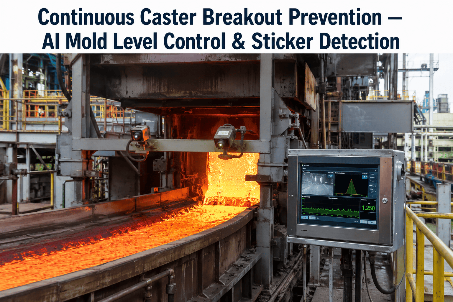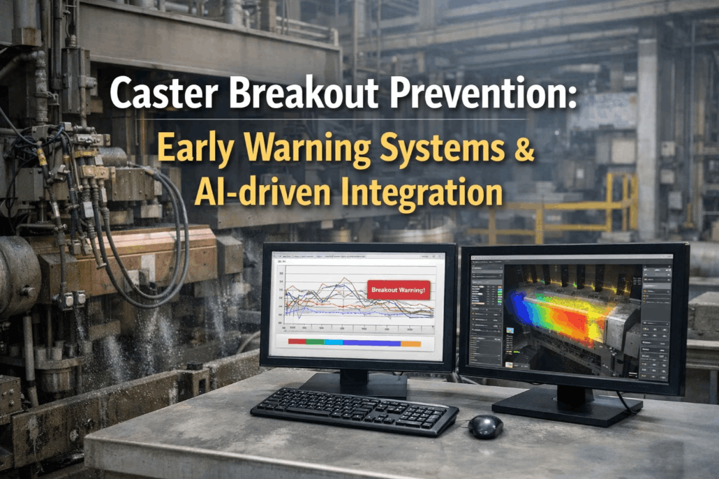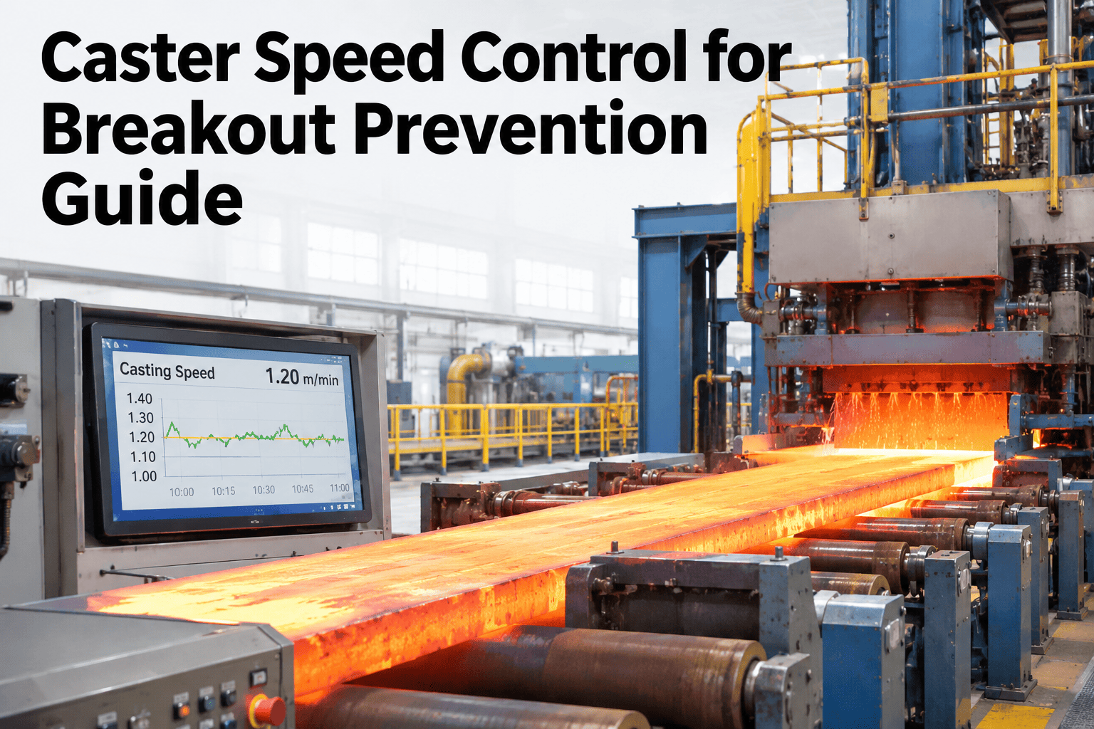
A breakout happens when the solidified shell inside a continuous caster mold tears and lets liquid steel escape at the mold exit. Faster casting speeds reduce shell thickness at the mold exit, which is exactly the mechanism that causes a breakout. Caster speed control for breakout prevention uses heat status and shell modeling to adjust casting speed dynamically, keeping every strand inside a safe margin instead of a fixed guess. Operations teams who want their own caster's safe margin reviewed can discuss their caster speed logic with the iFactory team.
The Shell Only Has to Be Thin in One Spot to Tear
iFactory, an on-premise AI platform for steel process control, reads mold heat status continuously and adjusts casting speed before a thin spot in the shell reaches the mold exit.
What Caster Speed Control Actually Does
Caster speed control for breakout prevention is a system that estimates shell thickness in real time and reduces casting speed when that thickness falls toward an unsafe margin. It is the direct countermeasure to the core physical relationship behind every breakout.
What Changes as Casting Speed Increases
Productivity pressure pushes casting speed up. Each increase trades a little shell thickness for a little more throughput, and the trade is not always visible until it fails.
| Casting Speed | Effect on Shell |
|---|---|
| Lower | More time to solidify, thicker shell at mold exit |
| Higher | Less time to solidify, thinner shell at mold exit |
Why Shell Thickness Is the Core Variable
A higher casting speed means less time inside the mold for the shell to solidify. Less time means a thinner shell at the mold exit, and a thinner shell is more likely to tear under ferrostatic pressure.
How Mold Thermocouples Carry the Signal
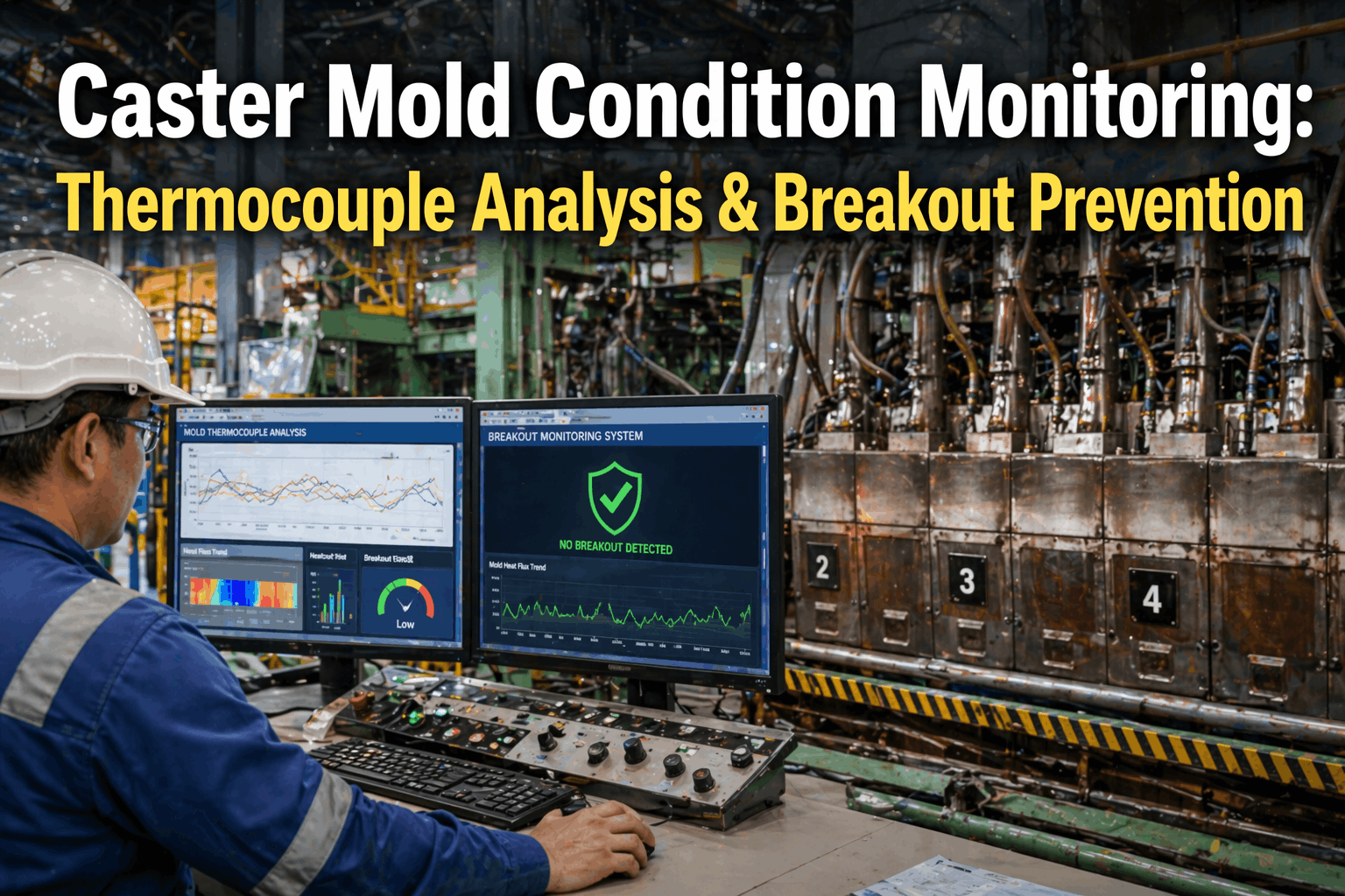
A grid of thermometers embedded in the mold wall reads temperature continuously. A developing thin spot shows up as a localized temperature deviation before it ever reaches the mold exit.
Check Your Own Caster's Risk Margin
Share your mold thermocouple data and current speed profile, and iFactory will show how a dynamic margin would have responded.
Why Start-Up Is the Highest-Risk Window
A meaningful share of breakouts across a typical caster's operating history occur specifically during start-up, before the process has settled into a steady state. The dummy bar and ramp-up period deserve their own conservative speed profile.
The Control Action Most Systems Rely On
Once a breakout risk is predicted, casting speed is the fastest lever available to the process. Slowing the strand gives the shell more residence time in the mold before the risk reaches the exit.
Dynamic Speed Adjustment Logic
When the system detects a developing risk, the response is not a full stop. It is a measured reduction that buys the shell more solidification time.
Fixed Margin vs Dynamic Margin
A fixed speed limit protects the worst-case grade and section, which leaves throughput on the table most of the time. A dynamic margin adjusts to what the mold is actually showing right now.
A Composite Scenario: Catching a Localized Thin Spot
A slab caster was running a routine grade change mid-shift. A single thermocouple near the mold's narrow face began drifting from its normal pattern while the rest of the grid stayed flat.
The system reduced casting speed by a measured amount rather than stopping the caster outright. The temperature pattern recovered within minutes, and speed ramped back up once confirmed.
Common Mistakes in Caster Speed Programs
Most breakout near-misses trace back to a small set of recurring program gaps rather than a genuinely unpredictable event.
| Mistake | Consequence |
|---|---|
| One fixed speed limit for every grade | Over-conservative on easy grades, risky on hard ones |
| Ignoring single-sensor deviation as noise | A real localized thin spot goes unaddressed |
| Same ramp profile for start-up and steady state | Start-up risk is not treated with the caution it needs |
Where iFactory AI Fits
iFactory reads mold thermocouple data continuously, models shell thickness against casting speed, and adjusts the speed profile automatically within operator-approved limits.
Continuous Shell Modeling
Shell thickness is estimated in real time from mold heat data.
Localized Deviation Detection
A single thermocouple drift is distinguished from normal grid noise.
Dynamic Speed Adjustment
Speed is reduced and restored automatically within approved limits.
What a Rollout Looks Like
Deployment starts with reading existing thermocouple and speed data, not with new hardware. The model is calibrated against the caster's own breakout history before any automatic speed adjustment goes live.
Frequently Asked Questions
How early can a breakout risk actually be caught?
Mold thermocouple deviation can flag a localized risk well before the thin spot reaches the mold exit, often with enough time for a measured speed reduction instead of an emergency stop. See detection timing on your caster.
Does speed reduction mean stopping the caster?
No, it is usually a measured speed reduction rather than a full stop, aimed at giving the shell enough extra time in the mold to recover a safe thickness before resuming. Ask support how limits are set for your grades.
Why does start-up need a separate speed profile?
A disproportionate share of breakouts occur during start-up, so a more conservative ramp profile is standard practice until the process reaches a settled steady state. Review your start-up profile with our team.
Can this replace our existing mold thermocouple system?
No, it reads and models the data from your existing thermocouple grid rather than replacing the sensors themselves, so existing hardware investment stays in place. Ask what connects to your current setup.
How much throughput can a dynamic margin actually recover?
It depends on how conservative your current fixed limit is relative to what the mold data actually supports, which is exactly what a first review is meant to establish. Model your own throughput margin on a short call.
Run Closer to the Real Limit, Not the Worst Case
Book a session with iFactory and see your own mold heat data modeled into a dynamic speed margin.