Every manufacturing quality program has a blind spot — not a failure of the inspection team, but a literal geometric constraint: the surfaces a single camera simply cannot see. Curved flanks, internal bores, undercut grooves, angled weld joints, and recessed pocket features are invisible from the front-facing position where most inspection cameras are mounted. The part passes. The defect ships. AI vision for multi-surface and complex geometry inspection resolves this by arranging calibrated multi-camera stations that cover all faces of a part simultaneously — fusing every viewpoint into a single pass/fail decision with full defect location mapping, at line speed. iFactory deploys these multi-view stations from camera selection through model training and production integration, with deployment specifications available at iFactory support.
Multi-Surface AI Inspection · Complex Geometry · 3D Vision
AI Vision for Multi-Surface and Complex Geometry Inspection
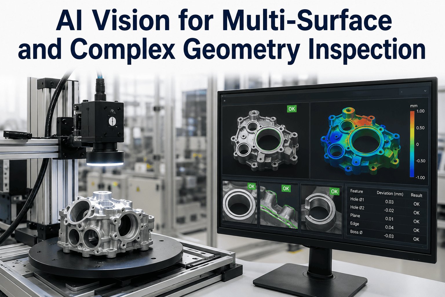
Multi-camera AI stations inspect every surface of a complex part simultaneously — curved flanks, internal features, undercuts, and hidden geometries — and deliver a single fused quality decision in under 100ms. No blind spots. No sampling assumptions. No defects reaching your customer from surfaces you could not see.
Surface Coverage by Camera Count
Complex geometry part with curved flanks, undercuts, and internal features
40%
Fewer escapes — hidden surface defects caught before shipping
<100ms
Multi-view inference fused into one decision in real time
16 views
Maximum simultaneous camera inputs per station
The Geometry Problem
Why Single-Camera Inspection Fails on Complex Parts
A single camera positioned above a production line is an engineering choice that works perfectly for flat, single-face parts. It is an inspection liability for anything more complex. Complex geometry parts — castings, machined housings, turbine blades, bevel gears, structural welds, automotive body panels — present surfaces at every angle, with features that are physically occluded from any single viewpoint. The defect that causes a field failure is rarely on the flat top face. It is on the curved flank, inside the bore, along the undercut groove, or at the fillet radius where stress concentrations are highest.
Curved Surfaces
Surface normal changes continuously — a scratch at 45 degrees to the lens axis reflects light away from the sensor and disappears from standard 2D imaging. Darkfield and structured light illumination required.
Turbine blades, bearing races, automotive body panels, forged connecting rods, gear tooth flanks
Internal Bores and Channels
The inside surface of a drilled bore is physically invisible from any external camera angle. Corrosion, machining chatter, tool marks, and burrs inside a bore can cause hydraulic leaks or structural failures that no external inspection will ever detect.
Hydraulic valve bodies, engine cylinder bores, fuel injector passages, surgical implant channels
Undercuts and Recesses
An undercut groove is by definition overhanging — the geometry blocks the direct line of sight from above. Oblique-angle cameras positioned below the plane of the feature are required. The defect depth in an undercut is often the critical measurement.
O-ring grooves, snap-fit features, keyways, piston ring grooves, T-slot channels
Angled Weld Joints
Fillet welds and butt welds at oblique angles present the inspection surface perpendicular to neither a top camera nor a side camera. Porosity, undercut, and lack-of-fusion defects at the weld toe require a camera positioned at the specific angle that makes the defect visible.
Structural steel frames, pressure vessel seams, exhaust manifolds, trailer hitches, pipe joints
Complex Pocket Features
Machined pockets with multiple floor levels and steep sidewalls create shaded zones where standard illumination does not reach. Coaxial illumination through the lens axis, or structured light projected from inside the pocket, is required to reveal surface condition at depth.
Milled housings, die-cast electronics enclosures, injection mold tool inserts, aerospace structural ribs
Bottom and Undersurface Features
The underside of a part resting on a conveyor is completely inaccessible to any overhead camera. Machining marks, datums, identification stamps, drain holes, and mounting pad surfaces can only be inspected by a camera positioned below the part — which requires either a transparent conveyor section or a flip/rotate handling step.
Engine blocks, cylinder head mounting faces, PCB solder side, press-fit datum surfaces
Station Architecture
How a Multi-Camera AI Inspection Station Is Built
A multi-surface inspection station is not a cluster of cameras pointed at a part. It is a precision optical system where every camera position, lighting type, and focal length is derived from the specific geometry of the part and the defect types that need to be detected on each surface. The architecture below describes the engineering decisions at each layer.
L1
Camera Layout and Coverage Mapping
The first design step is a coverage analysis of the part geometry — identifying every surface that needs inspection, the angles from which each surface can be seen, and the positions that cover the most critical areas without optical overlap that wastes processing resources. For a complex casting, this typically requires 6 to 12 camera positions. For a simple prismatic part with a problematic underside, it may require only a bottom-view addition to an existing overhead station. iFactory provides the coverage mapping as part of the pre-deployment station design.
Coverage analysis
3D geometry mapping
Blind spot elimination
L2
Lighting Engineering Per Surface
Each surface zone requires its own optimized illumination — the lighting that reveals a scratch on a curved polished surface is different from the lighting that reveals a crack inside a recessed pocket. Brightfield reveals surface stains and color anomalies. Darkfield reveals surface relief defects — scratches, dents, and bumps — by catching light scattered by the defect edge. Structured light (fringe projection) creates a phase-encoded pattern across the surface and detects 3D depth deviations of less than 0.025mm. Coaxial illumination eliminates shadows in deep recesses. Dome lighting eliminates specular reflections from curved metallic surfaces. Each camera in the station has its own independently controlled light source.
Darkfield
Structured light
Dome illumination
Coaxial lighting
L3
Sensor Selection by Surface Type
Area-scan cameras with resolutions from 5MP to 64MP cover flat surfaces and moderate curvature at high speed. Line-scan cameras are used for cylindrical surfaces, where the part rotates past a single scan line to build a 360-degree image without optical distortion. Laser triangulation sensors produce 3D point cloud data from cross-sectional profiles — ideal for undercut groove depth, step height, and warpage measurement. Structured light scanners capture full-surface 3D geometry in a single flash exposure — used for complex free-form surfaces that require form deviation measurement against a CAD nominal model.
Area scan up to 64MP
Line scan for cylinders
Laser triangulation
Structured light 3D
L4
Multi-View AI Fusion Model
Once images from all cameras are acquired simultaneously, a single deep learning model processes all views together rather than running separate models per camera. Cross-view attention allows the model to use information from one view to confirm or reject a candidate defect detected in another — a scratch on the curved flank that appears ambiguous from one angle is confirmed by a second view at a different angle. The model outputs a single pass/fail verdict per part, with defect type, severity, and 3D location mapped from the 2D image coordinates through the calibration matrices of each camera. Total inference time is under 100ms for up to 16 simultaneous views.
Cross-view attention
Single fused decision
3D defect location
Under 100ms inference
L5
Part Handling and Fixturing
Multi-surface inspection sometimes requires the part to move through the station — rotating 180 degrees to expose the underside, or indexing through multiple inspection positions. Part handling design is integral to the station architecture: a transparent conveyor section for underside inspection, a servo-controlled rotation stage for cylindrical parts, or a robot-loaded flip station for parts requiring top-and-bottom sequential coverage. The handling system must position the part repeatably within the tolerance of the optical calibration — typically within 0.2mm of the nominal position — so that defect locations reported by the system can be traced to physical coordinates on the part.
Rotation stages
Flip handling
Position repeatability
Robot integration
Your most critical defects are on the surfaces your current inspection cannot see. That is not a quality problem — it is a geometry problem. iFactory fixes it.
Multi-camera stations, engineered lighting per surface, and a fused AI model that covers every face of your most complex part. See the station design for your geometry in a 30-minute demo.
Lighting Science
The Illumination Choices That Make Defects Visible on Complex Surfaces
Lighting is not a setup detail in multi-surface inspection — it is the optical foundation. A defect that is invisible under one illumination mode becomes clearly detectable under a different mode. The decision matrix below maps defect types and surface characteristics to the correct lighting approach.
Lighting Mode
How It Works
Best Surface Type
Detects
Minimum Defect Size
Darkfield
Light strikes surface at a grazing angle. Only raised edges and surface relief scatter light back to the camera lens
Polished metals, ground surfaces, painted panels
Scratches, dents, raised burrs, engraving marks
0.05mm
Dome (Diffuse)
Illumination from all directions simultaneously. Eliminates specular hotspots on curved reflective surfaces
Chrome, polished castings, bearings, reflective curved parts
Surface stains, contamination, color deviation, micro-pitting
0.1mm
Structured Light
Fringe pattern projected onto surface. Phase shift analysis reconstructs 3D height map to sub-millimeter resolution
Free-form surfaces, complex castings, welds, gear teeth
Form deviation, warpage, profile mismatch vs CAD nominal, step defects
0.025mm depth
Coaxial
Light travels along the exact optical axis of the lens. Eliminates shadows at any depth — flat reflections only from surfaces perpendicular to the lens
Deep pockets, bores, recessed features, drill holes
Surface condition inside recesses, machining marks, burrs at hole exits
0.1mm
Backlight (Silhouette)
Light source behind the part. Part appears as a dark silhouette against bright background — edge profile is precisely measurable
Edge geometry, hole diameter, slot width, thin-walled parts
Edge chipping, notch defects, dimensional deviation on through-features
0.02mm
UV Fluorescence
UV illumination excites fluorescent dye penetrant or inherent material fluorescence. Cracks filled with penetrant fluoresce brightly against dark background
Castings, forgings, welds — subsurface crack detection
Surface-breaking cracks, porosity, seam defects, fatigue cracks
0.01mm
Industry Applications
Complex Geometry Inspection Across Industries: What Gets Inspected and Why It Matters
The parts most likely to cause field failures are the ones with the most complex geometry — and the ones that have historically been hardest to inspect completely. Each industry below has a geometry problem that single-camera inspection cannot solve.
Automotive Powertrain
6–10 cameras typical
Engine blocks, cylinder heads, crankshafts, connecting rods, valve bodies, transmission housings
Critical defect types:
Bore surface chatter marks, cross-hatch pattern deviation, casting porosity at pressure surfaces, thread damage in bolt bores, oil gallery burrs, deck face warpage, bearing bore circularity
A single bore surface defect on a cylinder wall can cause premature ring wear and oil consumption warranty claims costing an OEM $800 to $2,400 per vehicle returned.
Aerospace Turbine Components
8–16 cameras typical
Turbine blades, compressor vanes, disc assemblies, combustion liner panels, nozzle guide vanes
Critical defect types:
Leading and trailing edge nicks, tip cap cracks, cooling hole blockage, blade root fillet cracks, thermal barrier coating delamination, platform oxidation, erosion on the pressure and suction surfaces
Turbine blade inspection under AS9100 and NADCAP requires documented evidence of complete surface coverage — a regulatory requirement that mandates multi-view inspection architecture by design.
Medical Devices and Implants
4–8 cameras typical
Orthopedic implants, surgical instruments, catheter components, implant screws, hip and knee joint surfaces
Critical defect types:
Surface finish deviation on articulating surfaces (Ra deviation), machining burrs at edges, pitting on bone-contact surfaces, contamination particles, dimensional tolerance deviation on thread pitch and depth, coating integrity
FDA 21 CFR Part 820 and ISO 13485 require documented inspection of every critical surface. A burr on a surgical implant that causes tissue damage post-implantation results in FDA audit, product recall, and liability exposure.
Hydraulic and Pneumatic Components
4–8 cameras typical
Valve bodies, pump housings, cylinder bores, manifold blocks, fitting seats, O-ring groove profiles
Critical defect types:
O-ring groove depth and width deviation, bore surface roughness, port edge burrs, machining swarf inside drilled passages, seat concentricity, groove undercut radius, thread form damage
A bore surface roughness deviation of 0.5 micrometers on a hydraulic valve spool surface causes leakage that results in field returns, equipment downtime, and in mobile hydraulics, safety incidents.
Field Example
Bevel Gear Manufacturer: From Missed Flank Defects to 100% Surface Coverage in Six Weeks
A precision gear manufacturer producing bevel gears for agricultural and construction equipment was running a single overhead camera system that had been in place for four years. The system was effective at detecting tooth tip damage and top-face contamination, but had no coverage of the tooth flank surfaces — the curved contact faces that carry load in service. A wave of field warranty claims from a single equipment platform traced back to sub-millimeter scuffing marks on tooth flanks that the in-house inspection had not detected. Each gear had 13 to 14 teeth with two contact surfaces each — between 26 and 28 curved surfaces per part, all inaccessible from the existing overhead position.
iFactory designed a six-camera station: two angled cameras at 35 degrees from horizontal targeting the tooth flanks, two side cameras covering the mounting surfaces, an overhead camera maintaining existing top-face coverage, and a line-scan camera for the full 360-degree root fillet inspection as the gear rotated. Darkfield illumination was applied to the flank cameras to maximize scratch and scuffing visibility on the ground tooth surfaces. The AI model was trained on 1,400 labeled images across 9 defect classes. From station design to production qualification took six weeks. Flank surface defect detection rate moved from unmeasured to 99.3% on the seeded test set. Warranty claims from that equipment platform dropped to zero in the following two quarters.
0 to 99.3%
Tooth flank defect detection rate after multi-camera deployment
6 cameras
Station layout covering all 28 surfaces per gear
6 weeks
Station design through production qualification
Zero
Warranty claims from flank defects in the following 2 quarters
Frequently Asked Questions
What Engineers Ask Before Deploying Multi-Surface AI Inspection
How does the system produce a single pass/fail decision from 6 or more cameras without false rejects from conflicting results?
The multi-view AI model processes all camera images simultaneously through a shared inference pipeline rather than running separate decisions per camera and voting on the outcome. Cross-view attention in the model architecture allows each view's features to be cross-referenced against adjacent views — a candidate defect that appears in one view is confirmed or dismissed based on what other views of the same surface zone show. This fusion approach produces significantly fewer false rejects than per-camera voting because ambiguous detections in one view that are contradicted by a second view do not trigger an alarm. The output is one structured result per part: pass/fail, defect class, confidence score, and 3D location — regardless of how many cameras contributed to the decision. To see the fusion model architecture for your specific part geometry,
book a demo.
How many training images are needed for a multi-surface model covering 6 or more defect classes?
For most production-grade multi-surface applications, iFactory targets 500 to 2,000 labeled images per defect class per camera view. With transfer learning from pre-trained industrial inspection models, the lower end of that range is achievable for defect types with clear visual characteristics — a tooth flank scuffing mark or a thread root crack. High-variability defects with significant appearance differences across the surface (porosity that changes in size and shape depending on location on a casting) typically require the higher end of the range. Multi-surface parts have an additional consideration: defects that appear differently across different surface zones may need separate training sets per zone even when they are the same defect class. Total training data requirements are established during the pre-deployment feasibility assessment, and iFactory provides guidance on data collection strategy to reach the target within the available production run. For a data requirement estimate specific to your part, contact
iFactory support.
Can an existing single-camera inspection station be upgraded to multi-surface coverage, or does a new station need to be built?
In most cases, existing stations can be upgraded rather than replaced. The upgrade path starts with a coverage gap analysis of the current station — identifying which surfaces are currently being inspected, which are not, and what physical constraints exist for adding cameras in the required positions. For many parts, adding two to four cameras to an existing frame covering the blind surface zones is straightforward and can often be completed during a planned maintenance window without interrupting production. The more significant constraint is usually the enclosure: existing light-sealed enclosures designed for a single camera may not have physical space for angled camera mounts or the additional lighting required for new views. In those cases, a new enclosure is designed around the existing conveyor interface so the mechanical integration remains simple. The AI model is always retrained on the full multi-view input, even if the original single-camera model is retained as a starting point. Full upgrade scoping, including what is re-usable from the existing installation, is available through
iFactory support.
How does the station handle different part variants that have slightly different geometries?
Multi-surface AI inspection handles product variants through automatic part identification and program changeover. When a new part variant enters the station, a barcode reader or AI-based part recognition identifies the variant, and the inspection system switches to the corresponding camera configuration and AI model in under one second. Variants with the same general geometry but different dimensions — a family of bevel gears in different sizes, for example — can often share a single AI model with variant-specific tolerance parameters rather than requiring entirely separate models. Variants with significantly different surface geometry or defect classes require separate models but share the camera hardware through adjustable mounting positions. For high-mix production with frequent changeovers, the station design incorporates tool-free camera position adjustment so the optical configuration can be shifted between variant families without requiring engineering involvement. The practical limit for shared stations is typically 10 to 15 distinct variants before a second dedicated station becomes more economical. For a variant analysis of your specific product family,
book a demo.
What accuracy can AI vision achieve on curved and reflective surfaces compared to coordinate measuring machines?
For 3D surface form measurement using structured light, AI vision systems with calibrated fringe projection routinely achieve depth resolution of 0.025mm and positional accuracy of 0.05mm on curved surfaces — comparable to or better than CMM for most production dimensional inspection tasks. For surface defect detection (scratch, pit, crack, contamination), the relevant metric is detection sensitivity rather than dimensional accuracy: darkfield AI vision consistently detects surface relief defects down to 0.05mm on polished metallic surfaces, which is more sensitive than most manual visual inspection protocols. The key practical advantage over CMM is speed — a 3D structured light measurement completes in under 500ms per part, enabling 100% inspection of every part at production speed rather than the statistical sampling that CMM lab throughput forces. For reflective curved surfaces, polarization filters on the camera lens eliminate specular hotspots that would otherwise saturate the sensor and blind the model to the surface condition underneath. Specific accuracy requirements for your application can be assessed through a feasibility study — contact
iFactory support to start one.
Every Surface. Every Defect. Every Part. The Geometry Problem Is Solved — Let Us Show You How It Works on Your Part.
Multi-camera station design, engineered lighting per surface, cross-view AI fusion, and full 3D defect location output — built for your specific part geometry, deployed in six to ten weeks.