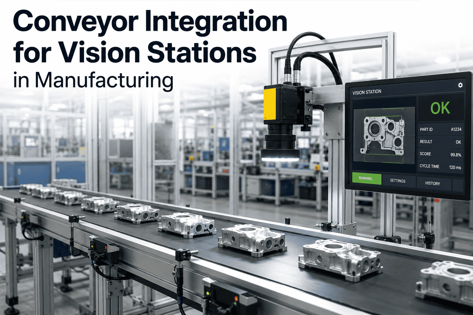
The camera is rarely the reason a conveyor vision project fails — the conveyor is. A vision model that classifies defects with 99% accuracy in the lab produces garbage results on the floor if the part arrives blurred, mistimed, or six millimetres off-center because nobody solved the transport problem first. Integration — how the part gets presented to the camera, how the trigger fires, how a reject gets pulled off the line without stopping everything behind it — is where most inspection projects actually live or die, and it's the part vendors talk about least. Encoder-based triggering alone can eliminate position variation as large as 30mm caused by fixed time-delay triggers that assume constant conveyor velocity, which never actually holds on a real production line. If your inspection accuracy problem is really a conveyor integration problem, book a 30-minute line audit and we'll help you find out.
Your Vision Model Isn't the Problem. How the Part Gets to the Camera Is.
Inspection accuracy is decided upstream of the AI model — by belt speed, trigger timing, part spacing, and how a reject gets pulled off the line without disrupting everything behind it.
Two Ways to Present a Part to a Camera
Every conveyor vision station makes one foundational decision before anything else gets designed: does the part stop for inspection, or does the camera capture it while it's still moving? That single choice cascades into everything downstream — throughput ceiling, mechanical complexity, camera specification, and total station footprint. Neither approach is universally correct; each fits a different production reality.
Why Timing Is the Entire Integration Problem
Once the stop-versus-fly decision is made, everything else in the integration comes down to one question asked over and over: how does the system know exactly when the part is in frame? Get this wrong and the symptoms look like an AI accuracy problem — blurry images, missed defects, inconsistent readings — when the root cause is a transport and triggering issue that no amount of model retraining will fix. The five-step sequence below repeats for every single part on the line, thousands of times a shift, and each step has to complete correctly and in order for the final reject decision to land on the right part at the right position.
Part Detected
A photoelectric sensor or encoder-linked position detector identifies the part entering the inspection zone — the starting reference point for every trigger calculation downstream.
Trigger Calculated
Encoder-based distance triggering fires the camera after a precise physical distance travelled — not a fixed time delay — so exposure timing stays accurate regardless of belt speed variation.
Image Captured
Exposure time is set short enough to freeze motion at line speed, with lighting synchronized to the same trigger so illumination is consistent frame to frame.
Decision Made
The inspection model classifies the part in milliseconds, well within the window before the part reaches the reject point downstream.
Action Executed
A diverter, pusher, or air-blast reject mechanism fires at the calculated position downstream, removing a failed part without disturbing the parts around it.
Five Integration Failure Points — and What Actually Fixes Them
The same handful of problems show up on almost every conveyor vision retrofit, regardless of industry or part type. None of them are AI model problems, and none of them get better by swapping cameras or retraining the classifier. They get better by fixing the physical transport and timing layer underneath the model.
| Symptom on the Floor | What Looks Like the Cause | What's Actually Wrong | The Fix |
|---|---|---|---|
| Blurry or streaked images | Bad camera or low resolution | Exposure time too long for actual belt speed | Shorten exposure, add strobed lighting synced to trigger |
| Part off-center or cropped | Camera misalignment | Fixed time-delay trigger, not accounting for speed variation | Switch to encoder-based distance triggering |
| Inconsistent defect scores | Model needs retraining | Lighting shifts between frames due to ambient interference | Enclose station, lock lighting to trigger, eliminate ambient light |
| Missed inspections on fast runs | Model too slow | Trigger window too narrow for part spacing variation | Widen trigger tolerance or stabilize upstream part spacing |
| Wrong part rejected downstream | Reject actuator malfunction | Position miscalculation between inspection point and reject point | Recalibrate encoder-to-actuator distance mapping |
A Composite Scenario: The Retrofit That Almost Got Cancelled
A mid-sized consumer packaging plant installed an AI vision system to catch label misalignment and seal defects on an existing conveyor running at roughly 40 packages a minute. In the vendor's lab demo, the system caught every defect flawlessly. On the actual production line, the accuracy dropped to something closer to 70%, with both missed defects and a stream of false rejects on perfectly good packages. The project was two weeks from being labeled a failure and shelved.
A line audit found the root cause had nothing to do with the AI model. The plant's conveyor ran on a variable-frequency drive that sped up and slowed down slightly to match upstream filling equipment, and the vision trigger was based on a fixed time delay calibrated at a single reference speed. Every time the belt sped up even slightly, packages arrived at the camera earlier than the trigger expected — sometimes catching only half the label in frame. The AI model was correctly classifying exactly what it was shown; what it was shown was frequently the wrong image.
The fix was mechanical and electrical, not algorithmic: an encoder was added to the conveyor drive shaft, and the trigger logic switched from a fixed millisecond delay to distance-based triggering keyed to actual encoder counts. Inspection accuracy on the same model, same cameras, same lighting, jumped to over 98% within a single shift of retuning. No line was ever shut down for retraining, because the model had never been the problem — the transport layer feeding it images had been.
The plant's quality manager later described the episode as the moment the team stopped treating the vision system as a black box and started treating it as one link in a longer mechanical chain — camera, trigger, transport, and reject actuator all had to agree on exactly where the part was at every instant, and once that agreement was restored, the AI model did exactly what it had been trained to do all along. The lesson generalized well beyond that one line: whenever a vision system underperforms its lab numbers on the floor, the first diagnostic question worth asking isn't about the model at all — it's about the belt.
Already Have a Vision Camera Underperforming on Your Line?
iFactory's integration engineers run a line audit before touching a single model — checking trigger timing, part spacing, lighting consistency, and reject synchronization first, because that's usually where the real accuracy gap is hiding.
Conveyor Types and What Each One Means for Vision Integration
Not every conveyor presents the same integration challenge, and the physical characteristics of the transport system directly shape camera positioning, lighting design, and trigger strategy. Retrofitting an existing line means working within whatever conveyor is already there — flexible integration approaches that accommodate flat, modular, inclined, and curved conveyor designs matter far more in a retrofit than in a greenfield build where the conveyor can be specified around the inspection requirement from day one. A vendor who quotes a single standard vision package without first asking which of these four categories your line falls into is quoting blind, and the mismatch usually surfaces only after installation, when the promised accuracy numbers don't show up on the actual floor.
Flat Belt Conveyors
The simplest integration case — stable, predictable part position, straightforward overhead or side camera mounting, and the easiest platform for encoder-based triggering.
Modular Belt Conveyors
Segment gaps can introduce lighting inconsistency and part micro-movement, requiring tighter exposure timing and often a diffused lighting enclosure to keep readings stable.
Inclined or Curved Sections
Camera angle and working distance shift along the incline, so inspection zones typically move to a flat run immediately before or after the curve rather than on it.
Indexing / Pallet Conveyors
Precision fixturing gives highly repeatable positioning, making this the natural fit for multi-camera stop-and-inspect stations needing several angles per part.
Reject Mechanisms: Getting the Bad Part Off the Line Without Stopping the Rest
Detecting a defect is only half the integration challenge — removing that specific part from the line, at the right position, without disturbing the parts ahead of or behind it, is a timing and mechanical problem of its own. The reject mechanism has to fire at a calculated position downstream of the camera, synchronized to the same encoder feed that triggered the inspection in the first place.
Diverter Arms
A pneumatic or servo-driven arm swings into the product path, guiding a failed part onto a separate reject lane. Common on packaging and box-handling lines.
Air-Blast Rejection
A precisely timed burst of compressed air knocks a lightweight defective part off the belt. Fast and contactless, ideal for small parts at high speed.
Pusher Mechanisms
A linear actuator physically pushes a failed part off the conveyor edge into a bin. Reliable for heavier or larger parts that air alone can't move.
Conveyor Stop-and-Hold
On lower-throughput or high-value lines, the entire conveyor halts on a failed detection, letting an operator manually remove and inspect the part.
What Belongs in the Integration Scope Before Anyone Talks About the AI Model
Vendors evaluating a conveyor vision retrofit that jump straight to camera and model specifications are skipping the part of the project most likely to determine whether the system actually works. A disciplined integration scope answers the transport and timing questions first, then selects hardware and models to fit what the physical line can actually deliver. Every one of the six checks below sounds mechanical rather than technological, and that's precisely the point — the physical realities of the line set a hard ceiling on what any camera or model can achieve, and no amount of software sophistication raises that ceiling once it's been set by an unmeasured belt or an unaccounted-for lighting shift.
Belt Speed and Variation
What is nominal line speed, and how much does it actually fluctuate during a shift? Variable-frequency drives synced to upstream equipment often vary more than plant documentation suggests.
Part Spacing Consistency
Do parts arrive at consistent intervals, or does spacing vary enough to confuse a fixed trigger window? Upstream bunching or gapping directly affects inspection reliability.
Available Working Distance
Is there enough physical clearance above or beside the belt to mount cameras and lighting at the correct focal distance without interfering with existing structure?
Ambient Light Conditions
Is the inspection zone exposed to shifting daylight or overhead lighting that changes through the day? Uncontrolled ambient light is one of the most common causes of inconsistent readings.
Distance to Reject Point
How much conveyor length exists between the inspection zone and the earliest possible reject point? This distance sets the hard ceiling on how much processing time the model actually has.
Existing Control Architecture
What PLC, encoder, and network protocol already runs the line — EtherNet/IP, PROFINET, EtherCAT? Integration is faster and cheaper when the vision system speaks the same language.
Retrofit vs. Greenfield: What Changes in the Integration Approach
Most conveyor vision projects are retrofits — adding inspection to a line that already exists and already runs production — rather than a new line built around inspection from the start. The integration discipline is different for each, and the retrofit case is both more common and more constrained, since the existing conveyor, control system, and floor layout are fixed points the vision integration has to work around rather than requirements it gets to define. A greenfield build gets to treat inspection as a first-class design requirement from the earliest engineering drawings; a retrofit has to treat inspection as a guest arriving into a house that was built for someone else, which is exactly why the audit step matters so much more in the retrofit case than in the greenfield one.
Frequently Asked Questions
The questions below reflect what plant engineers and quality leaders most often ask when scoping a conveyor vision integration, whether retrofitting an existing line or specifying a new one.
Can vision inspection be added to our existing conveyor without a full line shutdown?
In most cases, yes. Retrofit vision stations can typically be inserted into an existing conveyor, added to a robotic cell, or mounted above a manual workstation without requiring a full rebuild of the line. The installation is usually scheduled around a planned maintenance window rather than an extended shutdown, though the exact approach depends on how much of the existing control architecture — PLC, encoder, network — can be reused versus needs adding. Book a 30-minute audit to scope what's realistic for your specific line.
Do we need to slow down our conveyor to get accurate inspection?
Not necessarily. Fly-by inspection systems are designed specifically to capture accurate images of parts moving at full production speed, using encoder-based triggering and short exposure times to eliminate motion blur without requiring the part to stop or the line to slow. Whether fly-by is the right fit depends on the required inspection precision — very tight tolerance measurements sometimes still favor a brief dwell station — but for the majority of defect and presence checks, full-speed inspection is achievable.
Why is my vision system's accuracy inconsistent even though the lighting looks fine to the eye?
Human eyes adapt to lighting changes far more than a camera sensor does, so a shift that looks negligible to an operator walking past can be significant enough to alter a model's confidence scores. The most common causes are ambient daylight variation through the day, overhead fixtures on a different schedule than the inspection station, and reflective surfaces near the inspection zone catching stray light. Contact support for a lighting consistency check on your station.
How much distance do we need between the camera and the reject mechanism?
The required distance is a function of three numbers: conveyor speed, the model's inspection decision time, and the reject actuator's physical response time. At higher line speeds, even a fast model needs enough conveyor length between camera and reject point to guarantee the actuator can fire before the part passes it. This distance gets calculated during the integration scoping phase and is one of the first things an on-site audit measures.
What's the single most common mistake plants make when adding vision to an existing conveyor?
Specifying the camera and AI model before understanding the conveyor's actual speed variation, part spacing consistency, and existing control architecture. Plants that skip the physical integration audit and go straight to hardware selection are the ones most likely to see disappointing accuracy after installation — not because the model is wrong, but because it was never given properly timed, properly lit, properly positioned images to work with. Visit support for a pre-installation integration checklist.
Get the Transport Layer Right, and the AI Model Will Follow
iFactory's integration engineers start with your conveyor, your trigger timing, and your reject mechanism — not with a camera catalog. Book a 30-minute walkthrough and we'll map exactly what your line needs before recommending a single piece of hardware.