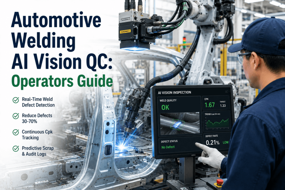
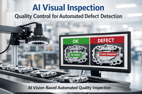
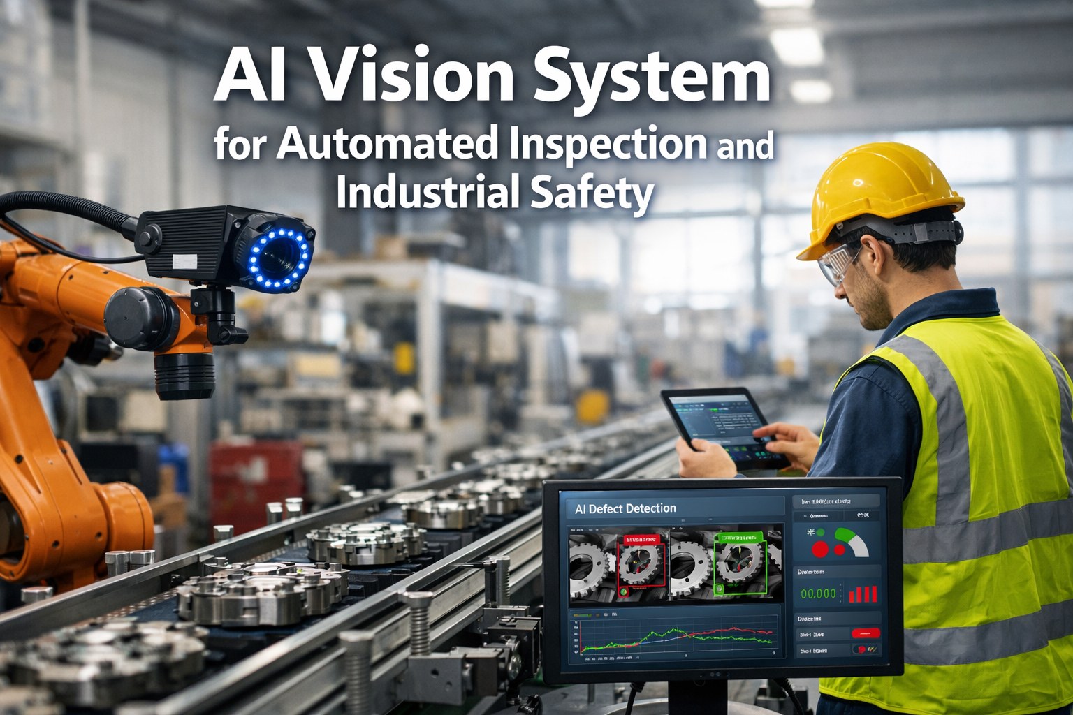
A weld can be structurally sound and still fail a customer's cosmetic standard, or it can look perfectly smooth on the surface while hiding a geometry defect that only shows up under load months later. Human inspectors, however experienced, are working against both fatigue and the physical limits of the eye — a porosity pit half a millimeter across, viewed under variable booth lighting for the eight-hundredth time in a shift, is genuinely hard to catch consistently. AI vision inspection brings two complementary capabilities to the weld station: pixel-level surface defect detection and precise bead geometry measurement, both applied to every single weld rather than a sampled few. This guide covers how the two work together, and if you'd like it running against your own weld samples, book a demo with iFactory.
Catch What Fatigue and Lighting Hide From the Human Eye
AI vision inspects surface defects and bead geometry on every weld, at line speed, with the same standard applied to the first weld and the ten-thousandth.
Two Inspection Disciplines, One Camera Pass
A weld can fail in ways the eye can catch and ways it fundamentally cannot. Surface defect detection handles the visible; geometry measurement handles the dimensional — and a complete inspection needs both running together, not one substituting for the other.
What the eye can see, but might miss
Porosity, spatter, undercut, cracks, and discoloration — defects visible on the surface but easy to miss under fatigue, poor lighting, or line-speed pressure.
What the eye simply cannot measure
Bead width, height, throat thickness, and profile angle measured to sub-millimeter precision — dimensional data no visual inspection can reliably estimate.
The Surface Defect Library
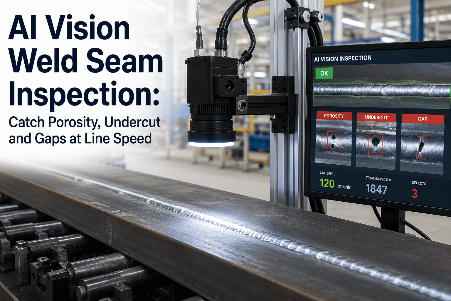
A properly trained AI vision model recognizes each common weld defect by its distinct visual signature, rather than applying one generic "looks wrong" threshold across every defect type.
Porosity
Small gas pockets appearing as dark pits on the bead surface, often clustered rather than isolated.
Spatter
Scattered metal droplets around the weld zone, distinguished from intentional bead texture by shape and location.
Undercut
A groove melted into the base metal at the weld toe, visible as a shadow line running along the bead edge.
Cracks
Fine linear discontinuities in the weld or heat-affected zone, often the most safety-critical defect class to catch reliably.
See Your Own Weld Defect Library in Action
iFactory trains the vision model on your actual defect samples, not a generic library, so classification accuracy reflects your specific process.
Measuring the Bead: What Good Geometry Looks Like
Structural weld standards specify acceptable ranges for bead dimensions, and AI vision measures each of these directly from the captured image rather than relying on a technician's visual estimate.
From Measurement to Classification Decision
Raw defect detections and geometry measurements only become useful once they're run against a defined acceptance standard and turned into a clear pass, review, or reject outcome.
Capture and measure
Camera captures the completed weld; the model simultaneously scans for surface defects and measures geometry against the calibrated frame.
Compare to standard
Detected defects and measured dimensions are checked against the specific weld standard configured for that joint type and application.
Classify the result
The weld is classified as pass, borderline for human review, or reject — with the specific parameter that drove the classification recorded.
Route and log
The result routes to the line controller for pass-through or hold, while the full measurement record logs against the unit's traceability data.
Frequently Asked Questions
How accurate is AI vision compared to a trained human weld inspector?
On surface defect detection, a well-trained AI vision model consistently matches or exceeds human accuracy specifically because it doesn't degrade with fatigue, shift length, or repetition the way human attention does — the model applies the identical standard to weld one and weld ten thousand. On geometry measurement, AI vision has a structural advantage over human visual estimation entirely, since it measures directly from calibrated pixel data rather than relying on eye judgment, which is inherently imprecise for sub-millimeter dimensional checks.
Can the system handle different weld types, like MIG, TIG, and spot welds, with one setup?
Different weld processes produce visually distinct bead characteristics, so the model needs to be trained or configured specifically for each weld type your line produces rather than assuming one generic model covers all of them. Most deployments handle multiple weld types by maintaining separate calibration profiles per process, selected automatically based on the station or work order rather than requiring manual reconfiguration between runs.
What happens to a weld the system flags as borderline rather than a clear pass or fail?
Borderline classifications route to a human reviewer with the captured image and the specific measurement that triggered the flag, giving the reviewer the exact information needed to make a fast, informed call rather than re-inspecting the weld from scratch. Over time, reviewing how these borderline cases get resolved also feeds back into refining the classification thresholds, narrowing the borderline category as the model calibration improves.
Does the inspection need to happen immediately after welding, or can it be done later in the process?
Inspecting immediately after the weld is completed, before the part moves to the next station, is strongly preferred because it allows an immediate hold and rework decision rather than discovering a defect after additional value has already been added downstream. Some processes do require a brief cooling period before the surface is stable enough to image accurately, which is a station-specific timing detail worth confirming during setup rather than a fixed universal rule.
How long does it take to get AI weld inspection running on an existing weld station?
A pilot on a single weld station, using existing defect and geometry samples for initial model training, typically takes three to six weeks from camera installation through validated go-live. Book a demo to scope the pilot timeline against your specific weld process and joint types.
Inspect Every Weld, Not Just a Sample
Book a 30-minute demo and see how iFactory catches surface defects and measures bead geometry on your own weld samples.