An electrical failure rarely starts as a failure. It starts as a connection running a few degrees warmer than it should, an insulation resistance reading that has been quietly declining for months, or a torque value that relaxed slightly during the first weeks after installation. None of these produce an alarm on their own. iFactory's electrical asset monitoring gives panels, motors, and connections a documented condition history, so a slow warning sign becomes a scheduled work order instead of an unplanned shutdown.
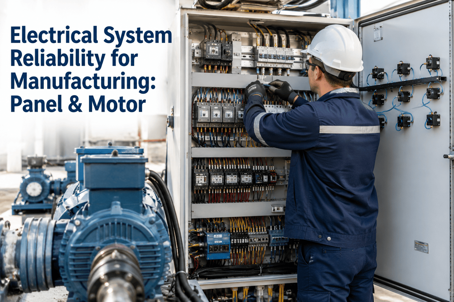
Electrical System Reliability for Manufacturing: Panel & Motor
Panel maintenance, motor testing, and connection integrity are three separate disciplines with three separate failure signatures. This guide covers what to test, how often, and what the readings actually mean for each one.
Why Electrical Failures Feel Sudden but Rarely Are
A breaker trips, a motor stops, a panel arcs — from the shop floor, electrical failures look instantaneous. From an inspection record, they almost never are. The underlying degradation mechanisms in electrical systems — rising connection resistance, declining insulation resistance, bearing-related winding stress — all generate a detectable signal well before the equipment actually fails. The gap between the first detectable signal and the eventual failure is the entire window a maintenance program has to intervene, and for most electrical failure modes that window is measured in weeks or months, not minutes.
That window closes for one of two reasons: either nobody is measuring the right thing, or the measurements exist but nobody is trending them. A single thermal scan or a single megger reading tells you the condition on that day. A trend across scans over months tells you whether a connection or a winding is degrading, and how quickly — which is the information that actually drives a maintenance decision.
The financial case for closing that window is not abstract. Electrical failures are consistently cited among the leading causes of unplanned downtime across manufacturing facilities, and reactive electrical repairs typically cost several times more than the equivalent planned intervention would have, once emergency labor, expedited parts, and cascading production loss are counted alongside the repair itself. A single prevented failure on a critical panel or motor routinely covers the cost of an entire year's testing program, which is why electrical reliability tends to be one of the higher-return areas of a broader maintenance strategy even before safety and insurance considerations are factored in.
Turn a Single Reading Into a Trend That Actually Predicts Failure
iFactory stores every thermal scan, megger reading, and torque check against the specific asset, so the next inspection compares against history automatically instead of starting from zero.
Panel Maintenance: Thermal Signatures and Connection Health
Electrical panels, motor control centers, and switchgear share a common failure pattern: developing problems generate heat before they generate a visible or audible symptom. A loose connection, a degrading contactor, or an overloaded circuit all increase electrical resistance at the fault point, and resistance under load produces heat — heat that is invisible to a walk-by visual inspection but clearly visible to an infrared camera.
Thermal problems only manifest when current is actually flowing, which means panels must be scanned during normal production, not during a shutdown. A de-energized inspection with covers removed can catch obvious physical damage, but it will miss the resistance-driven heating that is the leading indicator of an imminent connection failure. Scans should be performed by qualified personnel using appropriate PPE, with covers removed so the camera has a direct line of sight to breaker terminals, busbar joints, neutral and ground connections, and transformer terminations — the specific points where connection resistance concentrates.
A raw temperature reading means little without two reference points: the ambient temperature at time of scan, and the equivalent component's temperature elsewhere in the same panel under the same load. A connection running consistently several degrees above a comparable connection carrying similar current is a developing problem, even if the absolute temperature seems unremarkable. Baseline images taken when the equipment is known to be healthy, paired with an alarm threshold for each component, turn a subjective "does this look hot" judgment into an objective trigger for a work order.
Loose connections are the single most common root cause behind the thermal anomalies a panel inspection finds, and they are also one of the more preventable ones. Terminations must be tightened to the torque value specified by the equipment manufacturer, using a calibrated torque tool — hand-tight is not a verifiable or repeatable standard. Thermal cycling during the first month of operation causes conductor creep and stress relaxation, which is why best practice calls for re-verifying torque on power terminals after the first thermal cycle and then on a defined periodic schedule afterward. One important caution: re-torquing an already-seated connection to its full specified value can disturb a good termination rather than confirm it, so periodic checks are typically performed at a reduced percentage of the original spec, sufficient to detect looseness without over-stressing a connection that is already correctly seated.
Motor Testing: What Insulation Resistance and Vibration Actually Reveal
Roughly half of all motor faults are mechanical in nature, and the other half electrical — which is exactly why a motor testing program needs both vibration analysis and electrical testing, rather than relying on either one alone. Vibration analysis catches bearing wear, misalignment, and imbalance. Insulation resistance and related electrical tests catch winding degradation, contamination, and moisture ingress. Neither test substitutes for the other, because they detect fundamentally different failure mechanisms.
Insulation resistance testing, commonly called megger testing, applies a DC voltage between a motor's windings and its frame to measure how effectively the insulation is blocking current leakage. A commonly referenced rule of thumb sets minimum acceptable resistance at roughly one megohm per 1,000 volts of rated operating voltage, though IEEE Std 43 provides the governing formulas for a precise minimum by voltage class. A single reading establishes a baseline; a declining trend across repeated readings over months is the signal that actually matters, since it reveals moisture ingress, chemical contamination, or thermal degradation building inside the winding well before it becomes a visible fault. The Polarization Index — the ratio of the 10-minute resistance reading to the 1-minute reading — adds a second diagnostic layer: a PI value below roughly 2.0 indicates contaminated or moisture-saturated insulation even when the absolute resistance reading still looks acceptable on its own.
Vibration signatures typically appear weeks before a bearing failure becomes audible or the motor's insulation resistance shows any measurable decline, which makes vibration analysis one of the earliest available warnings for the mechanical half of motor health. A useful general threshold: vibration movement more than roughly 25% above the equipment's established normal baseline indicates looseness or developing mechanical wear and warrants investigation. Because bearing wear can also introduce rotor displacement that creates secondary vibration masking the original fault signature, trending vibration data over time is more reliable than reacting to any single reading in isolation.
Motor nameplates specify a normal operating temperature, and a thermal scan under normal running load should show the housing at or near that value, with internal hot spots — bearings, shaft couplings, terminal boxes — running distinctly cooler than the core motor temperature unless a fault is present. A motor running measurably hotter than its nameplate rating, or showing a hot spot at a bearing or coupling that is disproportionate to the rest of the housing, is signaling a developing problem well before it trips a thermal overload or fails outright.
Building a Criticality-Based Testing Schedule
Not every panel and not every motor deserves the same testing frequency, and a plant that tries to apply one uniform schedule across its entire electrical asset base usually ends up over-testing the equipment that matters least while under-testing the equipment that matters most. A criticality-based approach starts by ranking assets on two dimensions: consequence of failure, and rate of degradation.
Consequence of failure asks what happens if this specific panel or motor goes down unexpectedly — does it stop a single non-critical process, or does it halt an entire production line and everything scheduled behind it. Rate of degradation asks how quickly a developing fault on this asset typically progresses from a detectable signal to an actual failure — a lightly loaded distribution panel in a clean, climate-controlled area degrades far more slowly than a heavily loaded motor control center in a hot, dusty production environment. Combining these two dimensions produces a defensible basis for setting scan and test intervals: high-consequence, fast-degrading assets get the tightest schedule, while low-consequence, slow-degrading assets can be tested less frequently without meaningfully increasing risk.
This is also where a documented electrical maintenance program earns its value beyond pure reliability. Insurance auditors and authorities having jurisdiction increasingly expect to see three specific things during an electrical inspection: thermal scan reports showing a consistent testing history, torque and connection verification records, and documented proof that scheduled maintenance was actually completed on schedule rather than deferred. A criticality-based schedule that is followed and documented satisfies all three expectations simultaneously, while an ad hoc or undocumented approach — even one that happens to catch most real problems — leaves a facility exposed during an audit or after an incident.
Electrical Testing Reference: What to Check, How Often, and Why
| Test | What It Detects | Typical Frequency | Warning Signal |
|---|---|---|---|
| Thermal imaging (panels) | Loose connections, overloaded circuits, failing contactors | Annual to quarterly by criticality | Temperature rise above comparable load points |
| Torque verification | Conductor creep, thermal-cycle loosening | After first thermal cycle, then periodic | Movement detected below original spec |
| Insulation resistance / PI | Winding contamination, moisture, thermal aging | Annual, or per criticality schedule | Declining trend or PI below 2.0 |
| Vibration analysis | Bearing wear, misalignment, imbalance | Monthly to quarterly on critical motors | >25% above established baseline |
| Thermal imaging (motors) | Bearing friction, winding overheating, load imbalance | Quarterly under normal running load | Above nameplate rating or asymmetric hot spot |
One Platform for Panel Thermography, Motor Testing, and Torque Records
iFactory schedules each test on the right interval for its criticality class and keeps the full reading history on the asset record — so an auditor, an insurer, or a new technician sees the complete picture in one place.
Cable Management and Connection Integrity
Cables and terminations are the connective tissue between every panel and every motor covered above, and they fail through mechanisms that are easy to overlook because the cable itself is rarely the point of failure — the termination is. Loose connections are consistently cited among the leading root causes behind preventable electrical fires and equipment failures, which is precisely why NFPA 70B shifted in 2023 from a recommended practice to an enforceable maintenance standard, with torque verification, thermal scanning, and documented corrective action now expected components of a formal electrical maintenance program rather than optional best practice.
Beyond torque, physical cable condition deserves its own inspection line: chafing against a cabinet edge, kinking at a tight bend radius, or insulation cracking from heat or chemical exposure all create the same downstream risk as a loose termination — elevated resistance, localized heating, and eventually failure. Cable routing that keeps runs away from sharp edges, vibration sources, and heat-generating components reduces this risk at the design stage, but existing installations still need a periodic visual and thermal check to catch degradation that develops after the original routing was completed.
Cable and connection inspection also benefits from being tied to the same asset record as the panel or motor it feeds, rather than tracked as a separate, generic "cable management" line item. A termination that keeps showing up as marginal on repeated torque checks, or a cable run that consistently reads slightly warmer than comparable runs nearby, is telling a specific story about that specific asset — a story that only becomes visible when the readings are attached to the equipment and reviewed together over time, rather than scattered across disconnected inspection sheets.
Common Mistakes That Undermine Electrical Reliability Programs
Scanning panels de-energized, or during a shutdown. Resistance-driven heating only appears under load. A thermal scan performed with the equipment powered down or lightly loaded will miss the exact condition the scan exists to catch.
Re-torquing every connection to full spec on every inspection. A properly seated termination can be disturbed, not confirmed, by repeatedly applying full torque. Periodic checks are meant to detect looseness, not to reapply maximum force on every visit.
Treating a single insulation resistance reading as a pass/fail test. An absolute reading above the minimum threshold can still represent a motor in active decline if the trend is dropping. The direction of the trend line matters as much as any individual number.
Running vibration analysis without a documented baseline. A vibration reading is only meaningful relative to that specific asset's own established normal range — comparing across dissimilar equipment or skipping the baseline step makes the threshold arbitrary.
Using a megohmmeter on solid-state equipment. Applying megger test voltage to VFDs, PLCs, or other electronic drives can destroy semiconductor components. Insulation resistance testing is for windings and conductors, not electronic control equipment.
Electrical Reliability KPIs to Track
Unplanned Electrical Shutdowns
Failures not preceded by a documented thermal, torque, or insulation resistance finding. Every occurrence signals a gap in test coverage or interval.
Thermal Scan Compliance
Percentage of scheduled panel and motor scans completed within their defined interval, weighted by asset criticality.
Average Polarization Index
Fleet-wide average PI across monitored motors. A falling average suggests a systemic moisture, contamination, or environmental issue rather than an isolated asset problem.
Loose Connections Found per Scan Cycle
Count of terminations requiring correction during scheduled torque verification. Should trend downward as thermal-cycle relaxation is caught and corrected in the early service life of new installations.
Every catastrophic panel failure I've been called in to investigate had a thermal signature that would have shown up on a scan taken thirty, sixty, ninety days earlier. The physics doesn't allow for a truly sudden electrical failure — resistance builds heat, heat accelerates degradation, degradation increases resistance further, and eventually something arcs or opens. The only question is whether anyone was measuring during that buildup. Plants that treat thermography and megger testing as a compliance checkbox catch the obvious problems. Plants that trend the data catch the developing ones, which is where the real savings live.
Frequently Asked Questions
Frequency should be set by criticality and environment rather than a single plant-wide schedule. High-criticality panels — those feeding continuous production lines or safety systems — typically warrant quarterly scans, while lower-criticality distribution panels may only need annual scanning under a formal electrical maintenance program. NFPA 70B provides a risk-based framework for setting these intervals rather than a single fixed number for every facility. Book a demo to see how iFactory sets scan intervals automatically based on each panel's voltage class and criticality rating.
Polarization Index compares insulation resistance measured at one minute against the same reading at ten minutes, and a healthy winding shows resistance continuing to rise across that window as absorption current settles. A PI value falling below roughly 2.0 indicates the insulation is contaminated or moisture-saturated, even in cases where the raw resistance reading still technically exceeds the minimum threshold. This makes PI a more sensitive early warning than absolute resistance alone, particularly for motors operating in humid or contaminated environments. Book a demo to see how iFactory trends PI alongside absolute resistance for every motor in your program.
A termination that has already been correctly torqued and seated can actually be disturbed by repeatedly applying full manufacturer-specified torque during later inspections, since the conductor and connector have already settled into their compressed state. The safer periodic practice is checking at a reduced percentage of the original torque value — enough to detect real looseness without over-stressing a connection that never needed correction in the first place. This distinction between initial installation torque and periodic verification torque is an area where many maintenance procedures get it wrong. Book a demo to see how iFactory documents both installation torque and verification checks on the same asset record.
Neither test can substitute for the other, because they detect different failure mechanisms — vibration analysis catches the mechanical half of motor faults, primarily bearing wear, misalignment, and imbalance, while insulation resistance and Polarization Index testing catch the electrical half, primarily winding contamination and insulation aging. Since motor faults split roughly evenly between mechanical and electrical causes, a program relying on only one test type is structurally blind to the other half of likely failure modes. Book a demo to see how iFactory schedules both test types on a single unified motor health record.
NFPA 70B transitioned from a recommended practice to an enforceable standard in 2023, shifting its language from "should" to "shall" and giving authorities having jurisdiction and insurers a formal basis for expecting documented electrical maintenance programs. The change reflects how consistently preventable causes — loose connections and moisture ingress among the most common — have been found behind avoidable electrical failures and fires when maintenance documentation was reviewed after the fact. Book a demo to see how iFactory generates the documented condition history NFPA 70B compliance now expects.
Give Every Panel, Motor, and Termination a Documented Condition History
iFactory schedules thermal scans, torque checks, and motor testing by criticality, trends every reading against the asset's own history, and turns a crossed threshold into a work order automatically.