A factory deploying 20 AI inspection cameras can usually get away with a flat network and a single switch closet — the mistakes are forgiving at that scale. A factory deploying 120 cameras across a full production floor cannot: the same flat design that worked for the pilot now saturates uplinks, starves PoE budgets, and buries GVSP inference traffic behind general IT noise the moment every station goes live simultaneously. Across more than 120 factory AI deployments, the network backbone is the infrastructure layer most often designed for the pilot camera count and never re-architected before the full rollout, and that gap is where camera bandwidth math, switch placement, and PoE power budgets stop scaling linearly. See how iFactory's deployment engineering team designs backbone architecture for 100+ camera vision inspection networks before the scaling problems show up in production.
On-Premise AI & GPU Infrastructure · Network Design
Network Backbone Design for 100+ AI Cameras
Bandwidth math, switch placement, and PoE power budgeting for factory-scale machine vision networks — practical guidance from 120+ deployments where the pilot's flat network design didn't survive the full rollout.
Copper GigE distance limit — the constraint that forces every switch placement decision
24–48Cameras per access switch, typical
25%Recommended PoE power budget headroom
10 GbETypical uplink tier for aggregated camera traffic
120+Factory AI deployments this guidance is drawn from
Why This Isn't a Surveillance Network
AI Inference Cameras Behave Differently Than Security Cameras
Most network design guidance available online for large camera counts is written for security and surveillance deployments — motion-triggered recording, heavily compressed streams, occasional bursts of activity. A factory AI vision network built for continuous inference is a fundamentally different traffic pattern, and applying surveillance-network assumptions to it is the most common design error at scale, one that rarely surfaces until the deployment has already grown well past the pilot's camera count.
01
Continuous, Not Bursty, Bandwidth Demand
Inspection cameras stream continuously during production, not on motion trigger. A GigE Vision camera running full frame rate at inspection resolution sustains meaningful bandwidth for the entire shift, not in occasional spikes a network can absorb through statistical averaging.
02
Lightly Compressed or Raw Frame Data
Inference models frequently need higher-fidelity frame data than a compressed security stream provides — defect detection on a 0.1mm feature loses accuracy under aggressive compression, pushing actual bandwidth per camera well above what a comparable surveillance camera would consume.
03
Low-Latency Requirement Back to the GPU Rack
A security camera stream can tolerate seconds of buffering. An inspection camera feeding a GPU making a pass/fail decision before a reject-air blower fires cannot — network congestion that would be invisible in a surveillance system becomes a missed defect or a false reject in an inference system.
04
All Cameras Active Simultaneously
A surveillance network rarely has every camera streaming at full bandwidth at once. A production line with 120 inspection cameras has all 120 active simultaneously for the entire shift — the network has to be sized for full simultaneous load, not an average utilization assumption.
This distinction matters most at the design review stage, before any hardware is purchased. A network architect pulling switch specifications from a security-industry sizing guide will consistently undersize a factory vision network, because the assumptions baked into that guidance — occasional bursts, heavy compression, tolerance for buffering — are the opposite of what continuous, low-latency, high-fidelity inference traffic actually needs. The safest starting assumption for a factory AI camera network is that every camera in the deployment will be transmitting at its full configured bandwidth simultaneously for the entire production shift, and the backbone should be sized against that worst case rather than an average utilization figure borrowed from a different kind of network entirely.
The Bandwidth Math
What a Single Inspection Camera Actually Consumes
The starting point for any backbone design is an honest per-camera bandwidth figure, calculated from actual resolution and frame rate rather than a rule-of-thumb borrowed from a surveillance deployment. The table below models common inspection camera configurations against their sustained network demand.
Camera Configuration
Resolution
Frame Rate
Approx. Sustained Bandwidth
Standard Inspection, Compressed
2MP (1920×1080)
30 fps
25–40 Mbps
High-Resolution Inspection, Compressed
5MP
30 fps
50–80 Mbps
High-Resolution Inspection, Light Compression
5MP
30 fps
150–250 Mbps
Precision Defect Detection, Raw/Near-Raw
6.4MP (GigE Vision typical)
20–30 fps
300–500 Mbps
High-Speed Line Scan
Variable (line-based)
High continuous rate
Up to full 1 Gbps port saturation
The critical planning implication: a precision defect-detection camera running near-raw frame data can approach or saturate a single GigE port on its own, which is why high-fidelity inspection cameras are frequently given dedicated GigE or even 2.5GigE/5GigE connections rather than being oversubscribed on a shared switch uplink the way a compressed security camera safely could be. Mixing camera types within the same deployment is common — a plant might run compressed cameras for general line monitoring alongside near-raw precision cameras at critical inspection points — and the bandwidth table above should be applied per camera type individually rather than averaged across the deployment, since averaging masks the specific switches and uplinks that will actually see peak load. A network sized on a blended average will look adequately provisioned on paper while still saturating at the specific access switch handling the plant's highest-fidelity cameras, exactly the kind of localized bottleneck a whole-network average hides until it shows up as dropped frames on the production floor.
Topology Design
The Tree Architecture That Scales Past 100 Cameras
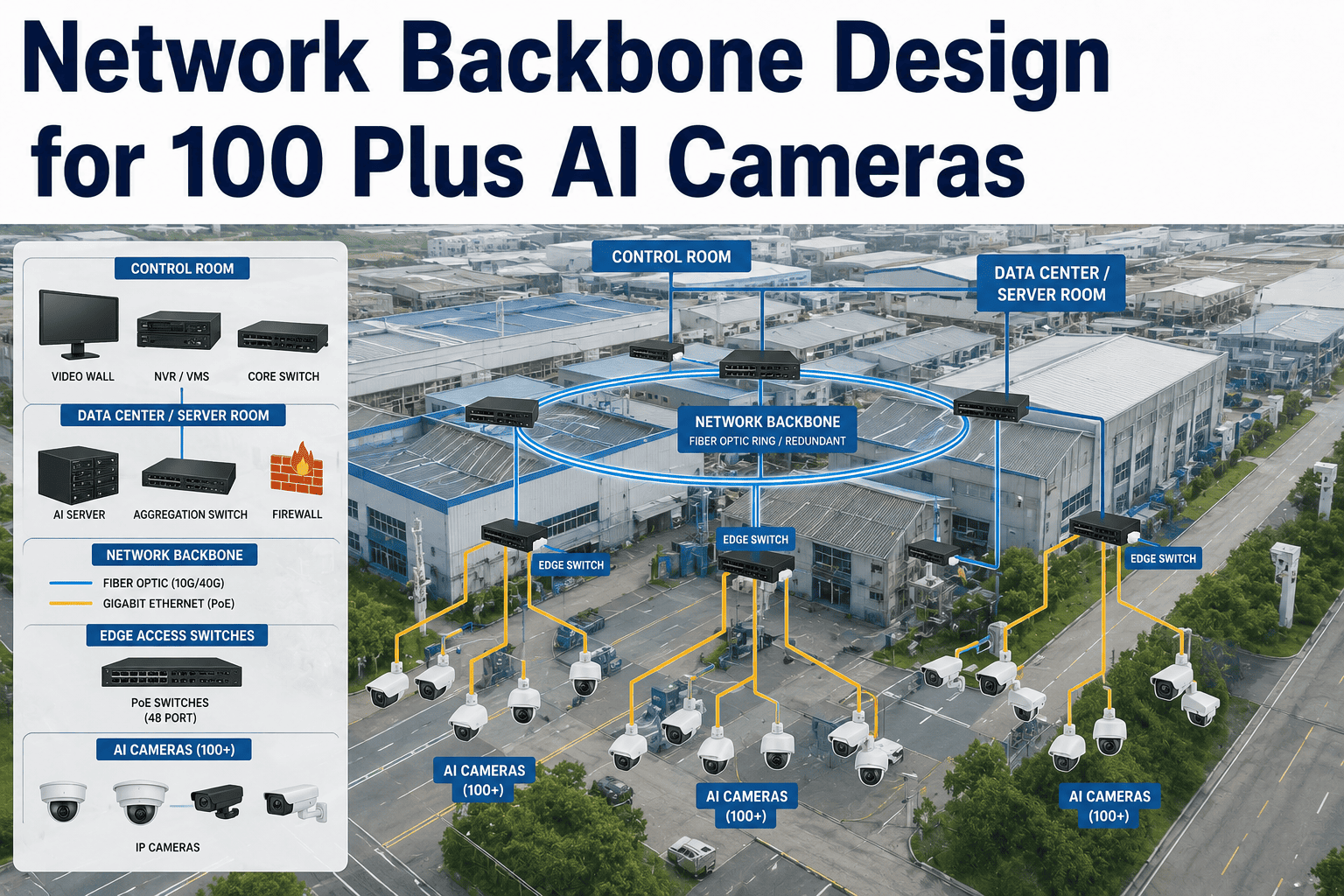
A three-tier tree topology — access switches near camera clusters, an aggregation layer collecting uplinks, and a core connection to the GPU rack — is the architecture that consistently scales cleanly past 100 cameras. Flat single-switch or daisy-chained designs that work at 20 cameras become the bottleneck at 100+, for a structural reason: a flat design forces every camera's traffic through a single point of aggregation with no intermediate layer to distribute the load, so the single uplink or single switch backplane becomes the ceiling on total deployment size regardless of how much capacity individual camera runs have.
The diagram below shows the pattern in practice — camera clusters connect to nearby access switches over standard copper runs within the 100-meter limit, access switches aggregate up to a core or aggregation switch over fiber, and the core switch maintains the single high-capacity connection into the GPU inference rack. This structure isolates problems: a camera cluster issue on one access switch does not propagate to the rest of the deployment, and adding a new zone of cameras means adding another access switch and fiber uplink rather than redesigning the entire network.
Switch Placement Rules
Where Access Switches Actually Go on the Factory Floor
Rule 1
The 100-Meter Copper Ceiling Drives Placement, Not Convenience
Standard GigE copper runs are limited to 100 meters. Every camera cluster more than 100 meters from a central closet needs its own access switch positioned within that radius, with fiber carrying the aggregated uplink back to the core — not a longer copper run that will fail intermittently under real conditions.
Rule 2
Size Access Switches to Cluster Density, Not a Round Number
A 24-port or 48-port access switch should be chosen based on how many cameras naturally cluster within that switch's practical cable-run radius on the actual floor plan, not an arbitrary standard port count — oversized switches waste ports and budget, undersized switches force awkward secondary runs.
Rule 3
Uplinks Need Real Headroom, Not Just Enough
An access switch aggregating 24 cameras at 150 Mbps sustained each represents roughly 3.6 Gbps of simultaneous demand — a single 1GbE uplink is inadequate. Size uplinks (typically 10GbE) with meaningful headroom above calculated peak simultaneous demand, not just barely enough to cover it.
Rule 4
Segment Camera Traffic Onto Its Own VLAN
Inference camera traffic should run on a dedicated VLAN separate from PLC/OT control traffic and general IT traffic. This prevents a general IT network event from disrupting inspection, and prevents inspection traffic bursts from interfering with time-sensitive PLC communication on the same physical infrastructure.
These four rules interact more than they might initially appear to. The 100-meter copper ceiling determines where access switches physically must sit; the switch's port count and uplink capacity determine how many cameras that switch can practically support once positioned; and the VLAN segmentation decision determines whether that switch can be shared industrial hardware serving both camera and OT traffic, or needs to be physically dedicated infrastructure. Working through the four rules in sequence, starting from the floor plan and the 100-meter constraint, produces a switch count and placement map that the bandwidth math from the previous section can then validate against actual uplink capacity before any hardware is ordered.
Design It for 100+, Not for the Pilot
The Backbone That Worked for 20 Cameras Rarely Survives the Rollout to 120
iFactory's deployment engineering team maps your actual floor plan, camera cluster density, and inspection resolution requirements to a switch placement and uplink design sized for the full rollout — not just the pilot line.
100+ PoE Cameras Is a Real Electrical Load, Not an Afterthought
Power over Ethernet simplifies camera installation by eliminating separate power runs, but at 100+ camera scale the aggregate power draw is a genuine electrical planning problem most switch closets were never wired for.
Worked Example: 120-Camera Deployment Across 5 Access Switches
Cameras per switch (24 cameras × 5 switches)24 cameras
Power draw per camera (PoE+, 802.3at, typical inspection camera)~12–15W sustained
Raw switch power budget needed (24 × 15W)360W minimum
Recommended budget with 25% headroom450W PoE budget per switch
Facility-Wide Implication
Total PoE load across 5 switches~2,250W minimum electrical circuit capacity
Existing closet wiring rated forVerify — many legacy IT closets are not
Action required before rolloutElectrical capacity audit per switch closet
This calculation is frequently skipped because PoE feels like a data problem rather than an electrical one — but a switch closet wired for a handful of low-power IT devices years ago was never sized for 24 cameras drawing 15 watts each continuously, and discovering the gap during installation rather than design causes some of the most disruptive delays in factory-scale camera rollouts. An electrical capacity audit of every planned switch closet, performed alongside the network bandwidth calculation rather than after it, catches this gap while it is still a design change instead of a construction change — the difference between updating a spec sheet and pulling new circuits into an active production facility.
Deployment Checklist
What to Verify Before the Full Rollout
These four checks address the specific gaps most commonly discovered after a phased camera rollout is already underway, when correcting them is far more disruptive than catching them during the design and pre-installation phase.
01
Calculate Bandwidth From Actual Camera Configuration, Not a Rule of Thumb
Confirm the actual resolution, frame rate, and compression setting for each camera type in the deployment and calculate sustained bandwidth from those real numbers — precision inspection cameras running near-raw frame data consume dramatically more bandwidth than a generic "IP camera" bandwidth estimate assumes, and that gap compounds quickly across 100 or more cameras.
02
Walk the Floor Plan Before Finalizing Switch Placement
Measure actual cable-run distances from proposed switch locations to each camera cluster — the 100-meter copper limit is a hard constraint, and factory floor obstructions, conduit routing, and cable tray paths often make the real distance longer than a straight-line measurement suggests.
03
Audit Electrical Capacity in Every Switch Closet
Verify each closet's electrical circuit can support the calculated PoE power budget with headroom, not just the switch's rated maximum — a switch capable of delivering 450W of PoE is irrelevant if the closet circuit it plugs into is only rated for 300W.
04
Test Under Full Simultaneous Load, Not Staggered Pilot Load
Before the full rollout goes live, test the backbone with every camera streaming simultaneously at full production frame rate — a network that performs fine with 20 of 120 cameras active during a phased pilot can still saturate the moment the remaining 100 come online together.
Field Perspective
“
The pattern I've seen repeat across dozens of rollouts: a pilot line runs beautifully with 15 or 20 cameras on a flat switch, everyone signs off on the design, and then the full-plant rollout to 120 cameras goes live and the uplink saturates within the first hour of full production. The pilot never exposed the problem because 20 cameras on a single switch with a decent uplink genuinely works fine — the failure mode only shows up at the scale the pilot was never designed to test. My rule now is simple: size the backbone math for the full rollout camera count from day one, even if the pilot itself only needs a fraction of that capacity, because retrofitting switch placement and fiber runs into a live production floor is far more disruptive, and far more expensive, than over-building the pilot's network by one tier from the start.
Priya Sharma-Delgado
IT/OT Network Infrastructure Engineer · 12 years designing industrial Ethernet and machine vision network architecture across automotive and electronics manufacturing
Common Questions
Frequently Asked Questions
How many AI inspection cameras can a single access switch reliably support?
For standard compressed inspection cameras in the 25 to 80 Mbps sustained bandwidth range, a 24 to 48 port access switch with an appropriately sized 10GbE uplink is typical, since 24 cameras at 80 Mbps each is roughly 1.9 Gbps of simultaneous demand — comfortably within a single 10GbE uplink's capacity. For precision defect-detection cameras running near-raw frame data at 300 to 500 Mbps sustained each, the practical camera count per switch drops significantly, sometimes to 12 or fewer per switch depending on uplink capacity, because a handful of high-bandwidth cameras can saturate the same uplink that would comfortably support 24 lower-bandwidth compressed cameras. Book a network design review to calculate the right camera-per-switch ratio for your specific inspection resolution requirements.
Should camera traffic share the same network as PLC and OT control traffic?
No — camera and inference traffic should run on a dedicated VLAN separate from PLC and OT control traffic wherever possible. Mixing the two creates two distinct risks: a bandwidth-heavy inspection traffic burst can introduce latency into time-sensitive PLC communication that expects deterministic response times, and conversely, isolating camera traffic prevents a general IT network event — a broadcast storm, a misconfigured switch, a security incident — from disrupting production-critical inspection. Physical segmentation with separate switch infrastructure is preferable where budget allows, but VLAN segmentation on shared industrial switches with appropriate QoS prioritization is a workable and common alternative.
When does a camera deployment need fiber instead of copper Ethernet runs?
Fiber becomes necessary whenever a camera or camera cluster sits more than 100 meters from the nearest switch, since that is the hard distance limit for standard copper GigE runs — attempting to exceed it with copper produces intermittent failures that are difficult to diagnose rather than a clean outright failure. Fiber is also frequently used for the uplink connections between access switches and the aggregation or core layer even within the 100-meter range, since it provides higher bandwidth capacity and better electrical noise immunity in an environment with the motor and welding equipment interference common on factory floors, conditions copper Ethernet was never designed to operate reliably alongside long-term.
How much PoE power budget headroom should a switch closet plan for beyond the calculated camera load?
A commonly recommended margin is roughly 25 percent above the calculated combined camera power draw, which accounts for cameras that draw more than their rated typical power during startup or under certain operating conditions, and leaves room to add cameras to that switch later without a full electrical re-audit. This headroom should be verified against both the switch's rated PoE power budget and the electrical circuit the switch closet itself is wired to — a switch capable of delivering the power is not sufficient if the circuit feeding that switch closet cannot support the combined switch and camera load safely.
What's the most common mistake when scaling a camera network from a pilot to full production?
Sizing the network backbone for the pilot's camera count rather than the full planned rollout count, which produces a design that performs well during the pilot phase and then saturates uplinks or exceeds PoE power budgets the moment the remaining cameras come online in production. Because a phased rollout often adds cameras gradually, the saturation point can arrive well after the pilot's success has already been used to justify the full deployment budget, making the resulting network redesign more disruptive than if the backbone had been sized for the target camera count from the initial design. Talk to deployment engineering about sizing your backbone architecture for the full rollout target before committing to switch placement.
Design for the Full Rollout, Not the Pilot
A Network Backbone That Scales to 100+ Cameras Without a Mid-Rollout Redesign
iFactory's deployment engineering team calculates real bandwidth demand from your actual camera specifications, maps switch placement against your floor plan and the 100-meter copper limit, and audits PoE electrical capacity — before the full rollout exposes a design built for the pilot.