The single most expensive mistake in factory construction is not overspending on equipment. It is pouring concrete before the network, sensor, and compute architecture has been designed — and then discovering, eighteen months into production, that adding AI-driven vision inspection to a single cell requires trenching floors, re-pulling armored cable, adding a second server room, and taking the line down for three weekends. Retrofitting AI-readiness into a running plant costs 4 to 8 times what it would have cost to build in from day one. If you are inside the design window for a greenfield facility, the decisions taken in the next 90 days will determine whether your plant is genuinely AI-ready in 2028 or whether you will be writing capital requests to catch up. To review your blueprint against the seven-layer AI-ready reference architecture, schedule a session with the iFactory design team.
Engineering Reference · Greenfield Factory Design 2026
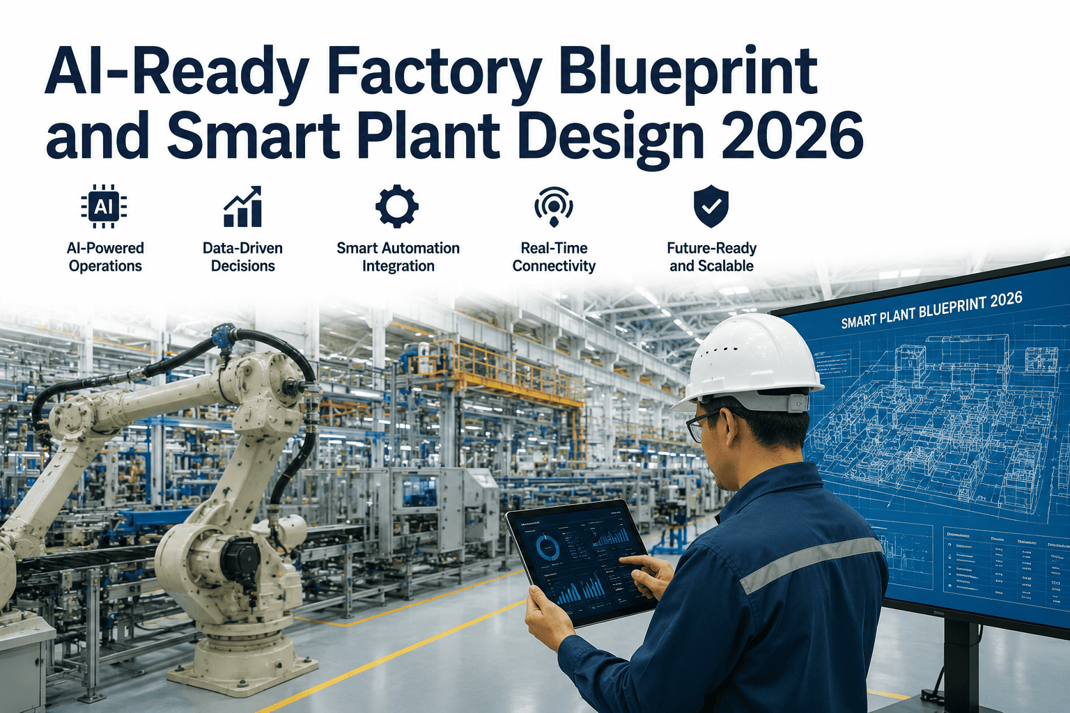
The AI-Ready Factory Blueprint: A Seven-Layer Reference Architecture for New Plant Construction
A design-phase specification for Project Directors, plant owners, and greenfield program leads. Every layer — from slab conduit routing to edge compute placement to digital twin data pipelines — sized and specified for AI workloads that will land in the plant over its first ten operating years.
4–8×
Retrofit cost multiplier versus building AI-ready from day one
7
Infrastructure layers to design in parallel — not in sequence
90 days
Design window during which most AI-readiness decisions are irreversible
10 yr
Planning horizon for compute, bandwidth, and sensor density growth
The Retrofit Trap
Why Greenfield Is the Only Cheap Window You Will Ever Have
Every AI capability you will eventually want in your plant — computer vision quality inspection, predictive maintenance, autonomous material handling, energy optimization, digital twin simulation — depends on three infrastructure primitives being present at the point of use: bandwidth to move data, compute to process it, and physical routing to deploy sensors. Building those primitives into a facility during construction adds 1 to 3 percent to the capital budget. Adding them to an operating plant three years later routinely runs 15 to 25 percent of the equivalent capital budget, plus production interruption cost, plus the design compromises forced by an existing layout that never anticipated them.
Slab & Structural Decisions
Conduit runs, sensor pit locations, cable tray hangers, camera mounting steel — all embedded in structure. Missing them means jackhammer, core drill, and steel modification later. Irreversible on day one; ruinously expensive on day 400.
Network Topology
Flat OT LANs cannot carry AI workloads. Segmented, VLAN-aware, TSN-capable networks with fiber backbones to each cell are a design decision. Retrofit means new switches, new pulls, downtime on every zone touched.
Power & Cooling Envelope
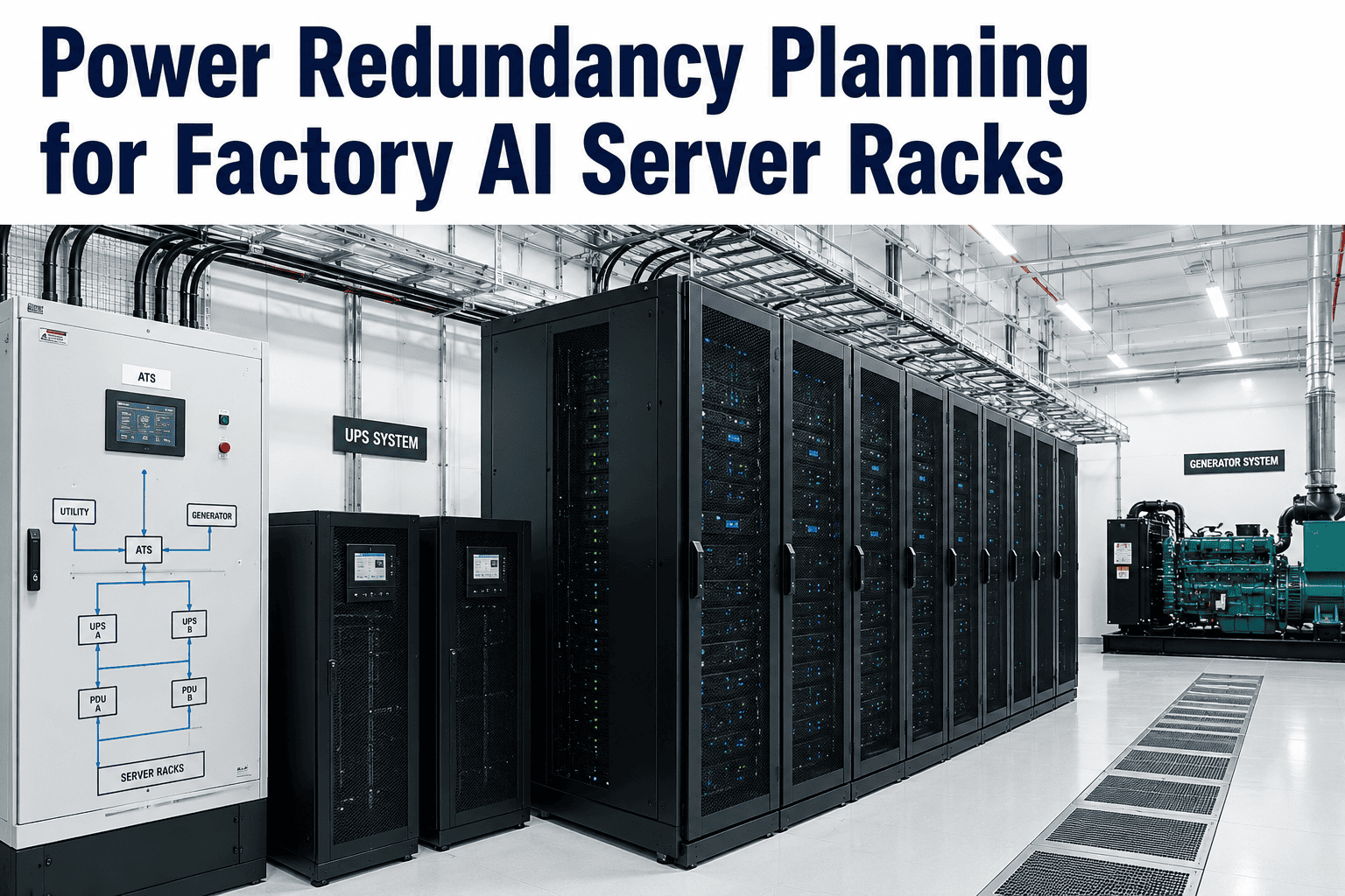
Edge server rooms and MDF/IDF closets need dedicated power, redundant UPS, and cooling sized 3–5× larger than a legacy telco closet. Under-sized rooms cannot host the compute AI needs. Expanding them means new HVAC circuits and switchgear.
Sensor Density Roadmap
Cameras, temperature probes, vibration sensors, and ultrasonics multiply over a plant's first five years. Cable tray fill, PoE budget per switch, and available conduit paths must be sized for that trajectory, not for opening day.
The Seven-Layer Reference Model
How to Design an AI-Ready Factory from the Slab Upward
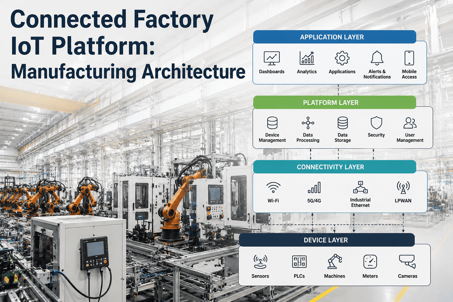
The reference architecture below is a design tool, not a product stack. Each layer must be sized, specified, and cross-checked against the layers above and below it before general arrangement drawings are frozen. A weak layer anywhere in the stack constrains every layer above it. The most common failure mode in greenfield projects is a compressed design phase in which layers 3 through 7 are treated as an IT afterthought while layers 1 and 2 are already being poured — locking in constraints that will haunt the plant for a decade.
Layer 01
Site & Structural Foundation
Owner: Civil & Structural Engineer + IT/OT Architect
The physical substrate of AI-readiness. Every conduit that must run under the slab, every camera mount that must be welded to structural steel, every pit or vault that must exist for sensor termination — all decided here, all irreversible after concrete pour.
Under-slab conduit density
2–4 conduits per 1,000 sq ft (fiber + copper + spare)
Sensor pit spacing
Every 30–50 ft on primary production aisles
Overhead cable tray capacity
Sized to 200% of Year-1 fill (leave 50% empty)
Camera mount pre-provisioning
Structural anchors above every workstation, not just Day-1 cells
Design freeze deadline: before foundation drawings issue for construction. After this point, changes cost 20–80× the design-phase cost.
Layer 02
Power & Environmental Envelope
Owner: Electrical Engineer + Facilities
AI workloads consume power the way legacy PLC systems never did. A single production-grade edge inference server draws 400–800W continuous. A vision-heavy plant may host 20–40 such servers across MDF/IDF closets. Cooling and UPS capacity must be sized against this future load, not against opening day.
MDF/IDF room count
1 MDF + 1 IDF per 50,000–100,000 sq ft production zone
Per-closet power provision
Minimum 30 kVA with A/B feeds and 30 min UPS
Cooling budget
3–5 tons per rack for AI edge compute (vs 1 ton for legacy)
Redundancy standard
N+1 minimum on cooling and power for edge server rooms
Design freeze deadline: before switchgear specifications go out for procurement. Under-sized rooms become a permanent constraint on how much AI the plant can host.
Layer 03
Network & Communications Fabric
Owner: IT/OT Network Architect
The layer where AI-readiness is most often compromised — and the layer whose deficiencies are hardest to disguise once the plant is running. A flat OT LAN with shared broadcast domains and best-effort switching cannot carry deterministic control traffic alongside high-throughput vision streams. The topology chosen here defines what workloads the plant can host for the next decade.
Backbone standard
Redundant 40G or 100G fiber ring between MDF and each IDF
Access-layer capacity
10G to every cell switch; 1G+ PoE++ to every device
Segmentation
Purdue-model VLAN separation with TSN on control tier
Wireless design
Wi-Fi 6E coverage plan + private 5G option for AMR/AGV zones
Design freeze deadline: before pathway routing is committed. Adding a fiber ring later means re-opening every cable tray and running new pulls through production aisles.
Blueprint Review Available
Your Layer 1–3 Decisions Freeze in the Next 90 Days — Get a Second Set of Eyes on Them
Most greenfield programs discover layer-mismatches during commissioning, when correction cost is highest. iFactory offers a design-phase blueprint review that stress-tests your seven-layer architecture against the AI workloads you will actually deploy in Years 3, 5, and 8 — before the concrete is poured and the switchgear is on order.
Layer 04
Compute & Edge Placement
Owner: IT/OT Architect + AI/ML Lead
Where inference runs determines what inference is possible. Vision workloads with a 30-millisecond decision budget cannot be served from a regional cloud region. Compute must be tiered — with cell-level edge devices for sub-100ms decisions, plant-level edge servers for aggregation and training, and cloud for long-horizon analytics and model management.
Tier 1 — cell edge
Fanless industrial PCs per cell, sized for 4–8 camera streams
Tier 2 — plant edge
GPU servers in MDF; sized for model training + fleet inference
Tier 3 — cloud
Model registry, long-horizon analytics, cross-plant benchmarking
Latency budgets
<30ms for control-adjacent AI; <200ms for quality decisions
Design freeze deadline: before rack elevations and closet HVAC are specified. Under-provisioned closets cannot be upgraded without demolishing walls and adding cooling loops.
Layer 05
Sensor & Vision Deployment
Owner: Automation Engineer + AI/ML Lead
Sensor and camera density grows non-linearly over a plant's first five years. Day-one deployments cover the obvious quality gates. Years 2 and 3 add process monitoring, energy metering, and vibration analytics. Years 4 and 5 add computer vision to secondary lines, AMR fleet perception, and predictive maintenance sensors on every rotating asset. Cable trays and PoE budgets sized for opening day guarantee the plant cannot host years 3–5.
Camera-per-cell target
Plan for 3–8 by Year 5; deploy 1–2 on Day 1
Sensor conduit reserve
50% spare capacity in every cell tray at commissioning
PoE budget per closet switch
Sized for 3× Day-1 device count
Lighting & optics standards
Machine-vision-grade lighting spec at every workstation
Design freeze deadline: before cable tray procurement and PoE switch sizing. Undersized here means either restricted AI adoption or a full re-cabling program in Year 3.
Layer 06
Data Platform & Historian
Owner: Data Architect + AI/ML Lead
AI models are only as good as the training data available to them. A plant with a fragmented data landscape — one historian for each vendor, no common asset model, timestamps in three different timezones — will spend 12 to 18 months on data plumbing before the first model reaches production. Design the data platform in parallel with the physical plant, not after commissioning.
Unified namespace
ISA-95 asset model; MQTT broker with sparkplug for OT data
Time-series storage
Plant historian sized for 5-year raw retention at full resolution
Data quality standards
Unit-of-measure enforcement; ISO 8601 timestamps; tag naming standard
Governance
Metadata catalog and access controls defined before Day-1 data flows
Design freeze deadline: before equipment procurement — vendor OPC UA compliance and tag naming standards must be enforceable in purchase orders.
Layer 07
Application & Digital Twin
Owner: Operations Lead + Simulation Engineer
The visible layer — MES, quality systems, maintenance systems, and the digital twin that ties them together. A digital twin built during design phase pays back three times: it validates the physical layout before construction, it commissions equipment against a virtual line before physical commissioning, and it becomes the operational simulation environment for the plant's entire life. Retrofit twins built after go-live rarely achieve this leverage.
Digital twin scope
Layout, material flow, and control-logic simulation from design phase
MES architecture
Cloud-native or hybrid; ISA-95 aligned; API-first for AI integrations
AI application scaffolding
Model registry, feature store, and MLOps pipeline defined pre-commissioning
Human interface standards
Andon, dashboards, and mobile HMI defined before UAT of Layer 6
Design freeze deadline: before commissioning schedule locks. Layer 7 gaps become "we will fix it after go-live" — which almost always means Year 2 or later.
Design Phase Decision Matrix
Which Decisions Freeze When — and Who Owns Them
The decision matrix below tracks the point-of-no-return for every AI-readiness decision across the greenfield timeline. Missing a deadline in this matrix is the mechanism by which good intentions become expensive retrofits.
| Decision |
Freeze Point |
Primary Owner |
Retrofit Cost Multiplier |
Blocks If Missed |
| Under-slab conduit routing |
Pre-foundation IFC |
Civil + IT/OT |
40–80× |
Sensor deployment, AMR guidance |
| MDF/IDF room sizing |
Pre-shell construction |
IT/OT + Facilities |
15–30× |
Edge compute density, cooling |
| Network fiber topology |
Pre-pathway install |
Network Architect |
10–20× |
All AI vision workloads |
| Cable tray sizing |
Pre-tray procurement |
Electrical + Automation |
6–12× |
Sensor density growth |
| Camera mount pre-provisioning |
Pre-steel erection |
Structural + AI/ML |
8–15× |
Future vision inspection cells |
| OPC UA compliance in specs |
Pre-equipment PO |
Automation Lead |
5–10× |
Data platform integration |
| Digital twin scope |
Pre-detail design |
Operations + Simulation |
3–5× |
Design validation, virtual commissioning |
| Tag naming standard |
Pre-programming |
Data Architect |
2–4× |
Historian usability, ML training data |
What The Blueprint Enables
AI Use Cases Unlocked by Each Layer Being Right
Year 1–2
Vision Quality Inspection
Camera-based defect detection at primary quality gates. Requires: Layer 1 mounting pre-provisioning, Layer 3 bandwidth, Layer 4 cell-edge compute, Layer 5 optics standards.
Year 2–3
Predictive Maintenance
Vibration and current-signature analytics on rotating assets. Requires: Layer 5 sensor conduit reserve, Layer 6 historian retention, Layer 4 plant-edge training capacity.
Year 3–4
Autonomous Material Handling
AMR fleets replacing forklifts on defined routes. Requires: Layer 1 floor markers, Layer 3 wireless coverage, Layer 4 fleet orchestration compute.
Year 3–5
Energy Optimization
Load balancing and demand-response driven by ML. Requires: Layer 5 sub-metering at every panel, Layer 6 real-time energy topic streams, Layer 7 optimization service.
Year 4–6
Closed-Loop Process Control
AI adjusting setpoints in real time based on quality and yield outcomes. Requires: Layer 3 TSN-capable network, Layer 4 <30ms inference, Layer 6 clean control-history data.
Year 5+
Generative Digital Twin
Simulation running continuously alongside physical plant, exploring what-if scenarios. Requires all seven layers functioning as designed, plus continuous data reconciliation.
From the Field
“
In twenty-three years of greenfield programs across three continents, I have never seen a plant fail because it over-invested in infrastructure at the design phase. I have seen dozens fail because they under-invested and then spent the next five years catching up. The pattern is always the same. The construction budget is under pressure. The IT and automation scope gets value-engineered. Cable tray sizes get reduced. Server closets get shrunk. The digital twin gets deferred to Phase Two. Two years later the plant is running production but cannot host the AI applications the business now needs, and the retrofit quotes come in at eight figures. The seven-layer blueprint exists because the industry has finally accepted that AI is not a Phase Two problem. It is a Layer Zero decision — every layer above depends on it, and the concrete is already curing while people are still debating it.
Dr. Ingrid Bergsson
Principal Greenfield Program Director · 23 years leading factory construction across automotive, pharma, and semiconductor · Former VP Manufacturing Engineering at a European automotive OEM · Board advisor on three industrial AI programs
Design Team Questions
Greenfield AI-Readiness — Frequently Asked
How much does AI-readiness actually add to the construction budget of a greenfield plant?
The incremental cost of building AI-ready from day one — larger cable trays, additional conduit runs, oversized MDF and IDF rooms, structured fiber backbone, camera-grade lighting, edge-server-ready electrical provision, and a designed data platform — typically lands between 1.5 and 3 percent of total construction capital. The comparison that matters is not against a bare-bones baseline; it is against the retrofit alternative. The same capabilities added to a running plant in Year 3 routinely consume 15 to 25 percent of an equivalent capital budget, plus 3 to 12 months of production disruption per zone touched. Every design review we run comes to the same conclusion: the marginal spend at the design phase is one of the highest-return decisions a Project Director ever signs. For a walkthrough of the cost model applied to a plant of your size and industry,
book a session with the iFactory design team.
What is the single most common AI-readiness mistake in greenfield factory design?
Under-sizing MDF and IDF closets — by a wide margin. The pattern is consistent across industries and continents. During design, the closets are sized based on legacy telecom and PLC needs, with power and cooling budgets that assume 1 to 2 racks of low-density equipment. When AI-driven vision and edge inference workloads land in Year 2 or 3, the closet needs 3 to 5 tons of cooling per rack, redundant 30 kVA power feeds, and physical space for 4 to 8 racks — and it has none of that. Expanding a closet retroactively means demolishing walls, adding HVAC circuits, and often losing floor space to a new equipment room. Designing closets for Year-5 compute density adds negligible construction cost and eliminates the single largest source of AI infrastructure regret. iFactory's design reviews always start with closet-level sizing before touching network topology.
Do we need a full digital twin during design, or can we defer it to a later phase?
A design-phase digital twin — even one focused only on layout and material flow, without full control-logic simulation — pays for itself before construction begins by exposing throughput bottlenecks, ergonomic issues, and material handling clashes while they are still cheap to fix on a drawing rather than expensive to fix on the floor. Full-fidelity twins that include control logic and virtual commissioning add further payback by shortening physical commissioning by 20 to 40 percent and by de-risking the ramp-up curve. Deferring the twin to Phase Two is one of the most common false economies in greenfield programs; the version built after construction rarely reaches the same fidelity and never captures the pre-construction design decisions it should have influenced. For a scoping conversation on where a design-phase twin fits in your program,
reach out to our support team.
How do we specify AI-readiness in equipment purchase orders when the OEMs themselves are inconsistent?
The most enforceable specification is a data-access clause rather than a capability claim. Require OPC UA compliance at a stated conformance level, require a documented tag list conforming to your naming standard, require MQTT publishing capability or a documented integration path, and require API access to any onboard analytics with no additional license fee. OEMs that cannot meet these clauses today will decline the bid — which is itself useful information. Those that can meet them will typically fold the requirement into their standard offering within one procurement cycle. The specification is what forces the market to become AI-ready alongside your plant. Without it, you are relying on marketing claims, which vary wildly from vendor to vendor and will not survive integration testing.
Our project timeline is compressed — is it realistic to design all seven layers in parallel with the physical building design?
It is not only realistic — it is the only workable approach for a modern greenfield program. Sequential design, where the physical building is completed first and the infrastructure layers follow, is the pattern that produces retrofit debt. Parallel design requires that the IT/OT architect, network engineer, data architect, and AI/ML lead sit inside the design integration meetings from schematic phase forward, with review authority over civil, structural, and MEP drawings. The additional design coordination effort typically adds 4 to 8 weeks to the design phase — and eliminates 12 to 24 months of post-commissioning retrofit work. iFactory frequently joins design integration teams as an embedded blueprint reviewer for exactly this reason.
Book a session to discuss how the review model would work on your project timeline.
Design Decisions Compound — Or They Compound Against You
Get the Seven Layers Right Before the Concrete Sets
iFactory's greenfield blueprint review is a structured design-phase engagement — not a sales conversation. Our team stress-tests your civil, network, compute, sensor, and data architecture against the AI workloads your plant will need to host in Years 3, 5, and 8. The output is a written blueprint annotation your design team can act on before the next IFC drawing package.