A maintenance lead at a 660 MW supercritical unit once told us, "I have ₹1.2 crores of vibration sensors installed across the plant, and I still can't tell you which boiler feed pump is going to fail next month." The sensors were not the problem — the selection was. Three of his eight BFPs had only single-axis accelerometers when triaxial was required. Two had no proximity probes despite running journal bearings where shaft displacement is the leading indicator. Four critical motors had no current-signature monitoring at all, leaving 15–20% of failure modes invisible. Spending more is not the answer — picking the right sensor for the right asset is. This page is the condition monitoring sensor selection reference we wish every power plant maintenance team had on day one.
Condition Monitoring Sensors for Power Plant Assets — The Selection Stack That Actually Works
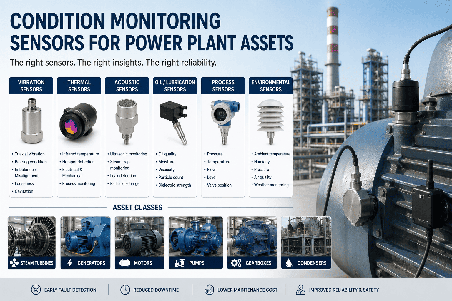
Triaxial accelerometers, proximity probes, ultrasonic, thermal, oil, partial-discharge, MCSA — eight sensor technologies, ten asset classes, one decision matrix. Built for maintenance teams who own the spare-parts budget and the next outage.
The Three Layers of Modern Condition Monitoring
A sensor on its own is just an electrical signal. A working condition monitoring program is three layers stacked together — sense, acquire, analyse. Failures in this stack are almost always at the joins, not in any single component. Getting the layer-to-layer specifications right is the difference between a program that catches failures and one that just generates noise.
Sense
The hardware on the assetPiezoelectric accelerometers, proximity probes, ultrasonic transducers, RTDs and IR cameras, oil-quality sensors, partial-discharge couplers, current transformers, and pressure sensors. Each technology answers a different physical question — bearing wear, shaft displacement, cavitation onset, hotspot growth, debris ingress, insulation degradation, electrical asymmetry, hydraulic deviation.
Right sensor for right failure mode
Acquire
Signal conditioning and edge gatewayIEPE signal conditioning at 4 mA constant current, 24-bit ADCs, anti-aliasing filters, sampling at 25 kHz or higher for bearing diagnostics, 100 kHz+ for ultrasonic. Edge gateways handle local buffering, time synchronisation, OPC-UA or MQTT publishing, and pre-trigger capture so a 10-second event is never lost to network jitter.
Lossless data path, deterministic timing
Analyse
FFT, envelopes, ML, dashboardsFFT and order tracking for rotating equipment, envelope demodulation for bearing defect frequencies, EWMA and CUSUM on trended overall values, and machine-learning classifiers trained on historical failure patterns. The output is not a number on a screen — it is a specific recommendation tied to a specific component on a specific asset.
Diagnosis, not just detection
Eight Sensor Technologies — Specifications, Coverage, and Cost Band
No single sensor catches every failure mode. The eight technologies below are the working set every power-plant maintenance program should understand, even if you only deploy three of them on Day 1. Specifications shown are typical industrial-grade values, not lab maxima.
Triaxial Piezoelectric Accelerometer
The workhorse of vibration monitoringBest for: Rotating equipment above 600 RPM — pumps, fans, motors, gas turbine bearings. Catches unbalance, misalignment, looseness, and bearing defects (BPFO, BPFI, BSF, FTF).
Proximity Probe (Eddy Current)
Shaft displacement, journal bearingsBest for: Steam and gas turbines, large pumps and compressors on journal bearings. Catches shaft orbit changes, rub, oil whirl, and bowed-shaft conditions that accelerometers cannot see.
Ultrasonic / Acoustic Emission
High-frequency stress and leaksBest for: Boiler tube leak detection, BFP cavitation, valve passing, electrical partial discharge, steam trap diagnostics. Catches what is mechanically inaudible but acoustically loud.
Thermal — IR Cameras + RTDs
Hotspot growth and bearing temperatureBest for: Boiler tube hotspots, generator stator winding, transformer bushings, switchgear connections, bearing temperature trends. Catches degradation that runs hot before it fails.
Oil Quality & Particle Counter
Lubricant condition and wear debrisBest for: Turbine lube oil systems, large pump bearings, gearboxes. Particle-count rise precedes audible bearing wear by 2–4 weeks; water ingress precedes corrosion by months.
Partial Discharge (PD) Sensor
Electrical insulation healthBest for: Generator stator windings, GT/GSU transformers, switchgear, MV motor terminations. Insulation failures show in PD activity 4–6 weeks before flashover.
MCSA — Motor Current Signature
Electrical fault detectionBest for: All HT motors above 100 kW — BFPs, ID/FD fans, CW pumps, coal mill drives. Catches the 15–20% of failures that mechanical vibration alone cannot diagnose.
Process & Pressure Sensors
Performance and hydraulic deviationBest for: Cross-correlating mechanical signatures with hydraulic/aero performance. The fastest ROI in the program — you already paid for these sensors, you just are not analysing them.
Asset to Sensor Coverage Matrix — Ten Asset Classes, Eight Technologies
This is the matrix that should hang on every maintenance manager's wall. Solid circle = primary sensor (deploy first); ring = secondary sensor (deploy when budget allows or risk justifies); blank = not applicable or low-value for this asset class. Use it as a starting reference, then tune to your plant's failure history.
| Asset Class | Triax Accel | Prox Probe | Ultrasonic / AE | Thermal | Oil Analysis | PD Sensor | MCSA | Process / Pressure |
|---|---|---|---|---|---|---|---|---|
| Steam Turbine (HP/IP/LP) | ||||||||
| Gas Turbine | ||||||||
| Generator (Stator + Rotor) | ||||||||
| Boiler Feed Pump (BFP) | ||||||||
| Condensate / CW Pump | ||||||||
| ID / FD Fan | ||||||||
| Coal Mill / Pulveriser | ||||||||
| Transformer (GT / GSU / UAT) | ||||||||
| HT Motor (above 100 kW) | ||||||||
| Boiler Tubes (waterwall / SH) |
Five Asset Classes Where Sensor Selection Matters Most
Not every asset deserves the full sensor stack. These five carry the largest share of forced-outage cost in a typical 500–800 MW thermal unit, and getting their sensor selection right delivers most of the program's value.
Steam Turbine — HP, IP, LP Rotors
Replacement cost: $20–30M per major rotor · Forced outage: 4–6 weeks
- Triaxial accelerometers at every bearing housing, 100 mV/g, stud mounted
- Proximity probes at each journal bearing, X-Y configuration for orbit analysis
- Keyphasor / tachometer for order tracking and balancing
- Online oil particle counter and water-in-oil sensor on lube system
- RTDs in every bearing housing + IR camera on casing for thermal trending
- Performance trending — steam conditions, stage pressures, efficiency
Boiler Feed Pump (BFP)
Replacement cost: $300K–700K · Outage if failed: 4–8 days
- Triaxial accelerometer at both pump and motor non-drive-end bearings
- Proximity probes on journal-bearing units; not needed on rolling-element
- Contact ultrasonic transducer for cavitation onset detection
- MCSA on motor for stator and rotor fault detection
- Suction and discharge pressure, plus flow — for hydraulic deviation
Generator — Stator and Rotor
Rewind cost: $5–15M · Outage if failed: 6–12 weeks
- Triaxial accelerometers at both end bearings (rotor mechanical health)
- Partial discharge sensors on stator phase leads, HFCT or capacitive coupler
- Distributed temperature sensing on stator winding hot spots
- MCSA on the field circuit for shorted-turn detection
- Hydrogen purity, seal oil pressure for hydrogen-cooled units
Generator Transformer (GT / GSU)
Replacement cost: $3–8M · Lead time: 18–24 months
- Online dissolved gas analyser (DGA) for arcing and overheating detection
- Partial discharge sensors — HFCT and UHF probes
- IR thermography on bushings, tap changer, radiator headers
- Bushing capacitance and tan-delta monitoring
- Oil quality — moisture, dielectric strength, particle count
ID / FD Fans — Forced and Induced Draft
Replacement cost: $400K–800K · Outage if failed: Unit derate or full trip
- Triaxial accelerometer at every bearing — fan and motor ends
- MCSA on motor — broken rotor bar is the #1 ID fan failure mode
- Inlet damper position, fan static pressure, motor current for performance
- Bearing temperature RTDs; oil sampling quarterly for splash-lube units
Six Mistakes Maintenance Teams Make During Sensor Deployment
Most failed condition monitoring programs do not fail because the wrong sensor was bought. They fail because the right sensor was installed badly, integrated badly, or interpreted badly. These are the six most common — and most expensive — mistakes we see during plant walkdowns.
Magnetic mount where stud mount is required
The mistake: Magnetic mounts are convenient but cap the usable frequency response at roughly 5 kHz. Stud-mounted gets you to 10–15 kHz, which is exactly where bearing defect frequencies live.
The fix: Stud-mount every permanent accelerometer on critical assets. Reserve magnetic mounts for handheld route data.
Single-axis where triaxial is required
The mistake: Single-axis sensors save cost but force you to assume the dominant fault direction. Misalignment shows in radial, axial, or both depending on geometry — single-axis can miss it entirely.
The fix: Use triaxial on every critical asset. Single-axis is acceptable only for handheld surveys.
No tachometer reference
The mistake: Vibration without RPM is a meaningless number. Order tracking, balance calculations, and resonance identification all require a phase-referenced tach signal.
The fix: Install a keyphasor on every critical rotating asset. One optical sensor per shaft is enough.
Cable shielding ignored, ground loops everywhere
The mistake: Sensor cables run alongside motor power leads or close to VFD outputs. Result: 50/60 Hz hum, harmonics, and false-positive bearing-defect signatures from electrical noise.
The fix: Dedicated cable trays for signal lines, twisted shielded pair with shield grounded at one end only.
Wireless used where wired is required
The mistake: Wireless MEMS sensors are good for non-critical assets and route data. They are not appropriate for critical machinery where you need 25 kHz continuous sampling and lossless data path.
The fix: Wired ICP / IEPE on critical assets, wireless MEMS on tier-3 monitored. Match the technology to the criticality.
No baseline data before alerts go live
The mistake: Alerts switched on within days of sensor commissioning. Every minor variation generates a notification, operators stop trusting the system, the program collapses.
The fix: Three to six months of baseline collection in advisory mode. Calibrate thresholds against real data, then enable alerting.
Get an audit of your existing sensor coverage
We walk down your plant, map your current sensor stack against the criticality matrix, identify the gaps that are costing you outages, and quote the right-sized program — without selling you sensors you do not need.
- Asset-by-asset coverage audit
- Gap analysis vs failure history
- Phased deployment plan by criticality
- Mounting and integration specifications
- Pre-configured NVIDIA AI server, racked and ready
- Live in 6–12 weeks with operator training
Three-Tier Criticality Framework — Where to Spend, Where to Skip
A 660 MW unit has 800+ rotating and electrical assets. You cannot sensor all of them — and you should not. The three-tier approach below is how mature maintenance programs allocate the condition-monitoring budget.
Continuous, full stack
Assets whose failure causes unit outage or a safety event. Roughly 10–15% of the asset population, 70% of the sensor budget.
- Steam and gas turbines
- Generators and GT / GSU transformers
- Boiler feed pumps (running set, not standby)
- ID / FD fans
- Coal mills
Periodic, focused stack
Important assets with redundancy or longer mean-time-to-failure. Roughly 25–30% of the population, 25% of the budget.
- Standby BFPs and CW pumps
- Auxiliary transformers
- HT motors above 100 kW
- Heat exchangers and large valves
Route-based or wireless
Everything else — auxiliaries, balance-of-plant. Roughly 55–60% of the population, 5% of the budget.
- Service-water and instrument-air compressors
- LT motors below 100 kW
- HVAC fans and chillers
- Small pumps and blowers
Implementation Roadmap for Maintenance Teams
A condition monitoring program that survives turnover and tariff pressure has six phases. Skip phase 2 or phase 4 and the program quietly dies within 18 months — we see it every quarter on plant audits.
Criticality Ranking Week 1–2
Rank every rotating and electrical asset by failure cost. Tier 1 / Tier 2 / Tier 3 classification driven by historical outage data, not opinion. Sign-off from operations, maintenance, and the asset manager.
Sensor Selection and Procurement Week 3–6
Apply the asset-sensor matrix. Specify mounting, cable specs, and gateway requirements. Procure to industrial-grade specifications — IP67, hazardous-area approvals where needed, 10–20 year service life.
Mechanical and Electrical Installation Week 7–14
Drilled and tapped studs for accelerometers, threaded mounts for proximity probes, cabling on dedicated trays, gateway commissioning. Most work during normal operation; only proximity probes need a brief stop.
Baseline Data Collection Week 15–26
Three to six months of in-control operation per asset. Stratify by load condition. No alerts during this period — only data quality checks and sensor health verification.
Advisory-Mode Pilot Month 7–9
Alerts go live in advisory mode. Maintenance team reviews every alert against ground truth. False-positive rate calibrated below 5% per asset before any protocol changes.
Operational Integration Month 10+
Critical alerts codified into the work-order system. Monthly asset health reports become standing items in the maintenance planning meeting. Re-baseline annually as equipment ages.
Condition Monitoring Sensors — Common Maintenance Questions
Do I need triaxial accelerometers everywhere, or are single-axis acceptable?
Triaxial is the default on every Tier 1 and Tier 2 asset. The marginal cost over single-axis is small — typically 30–40% more per sensor — and you eliminate the assumption about fault direction that single-axis forces on you. Single-axis is acceptable only for handheld route surveys on Tier 3 equipment.
Can wireless sensors replace wired ICP accelerometers on critical assets?
Not yet. Wireless MEMS sensors are excellent for tier-3 monitoring and route data, but their sampling rate, frequency response, and battery-driven duty cycle do not match what bearing-defect diagnostics require on critical assets. Use wired ICP for Tier 1, wireless MEMS for Tier 3, with Tier 2 as a judgement call based on asset criticality.
How do I justify the cost of MCSA on top of vibration monitoring?
MCSA catches the 15–20% of motor failure modes that vibration cannot see — broken rotor bars, shorted stator turns, air-gap eccentricity. The sensor is essentially free (you use the existing CT secondary), so the cost is the analyser and integration. On a 5 MW BFP motor, one prevented failure typically pays for MCSA across the entire fleet.
What does proper proximity probe installation require?
A drilled and tapped port through the bearing housing, the probe set to a 50 mil (1.27 mm) gap from the shaft target area, and the driver electronics mounted within 5 metres of the probe via a low-capacitance cable. X-Y orientation (two probes at 90°) is mandatory for shaft orbit analysis. Plan installation during a planned outage — this is not a running-machine job.
How long do industrial-grade sensors last?
Wired piezoelectric accelerometers and proximity probes routinely deliver 15–20 years of service. Wireless battery-powered sensors deliver 3–7 years per battery. Online oil analysers and PD sensors need re-calibration every 2–4 years. Budget for full sensor refresh on a 15-year cycle for Tier 1 assets.
Do we need to buy NVIDIA AI servers separately?
No. The fully-loaded AI server is supplied pre-configured and pre-loaded with the asset-monitoring dashboards, signal-processing pipeline, and alert rule engines. Rack it, connect power and Ethernet, and the system goes live. Cabling, gateway integration, DCS/historian connectivity, operator training, and 24×7 remote monitoring are all included in the package.
What is the typical timeline from contract to first sensor live?
Live in 6–12 weeks for a single-station pilot covering Tier 1 assets. Three-phase delivery: weeks 1–4 — criticality ranking, sensor procurement, gateway install. Weeks 5–8 — mechanical and electrical installation, baseline collection starts. Weeks 9–12 — advisory-mode go-live and operator training. Full operational integration by month nine to twelve.
Right Sensors, Right Assets, Right First Time
Hardware + software bundle. Pre-configured NVIDIA AI server, racked and ready, pre-loaded with asset-monitoring dashboards. Cabling, mounting, sensor integration, historian connectivity, operator training, and 24×7 remote monitoring all included. Live in 6–12 weeks. Trusted by 1000+ industrial clients with 99.9% uptime.