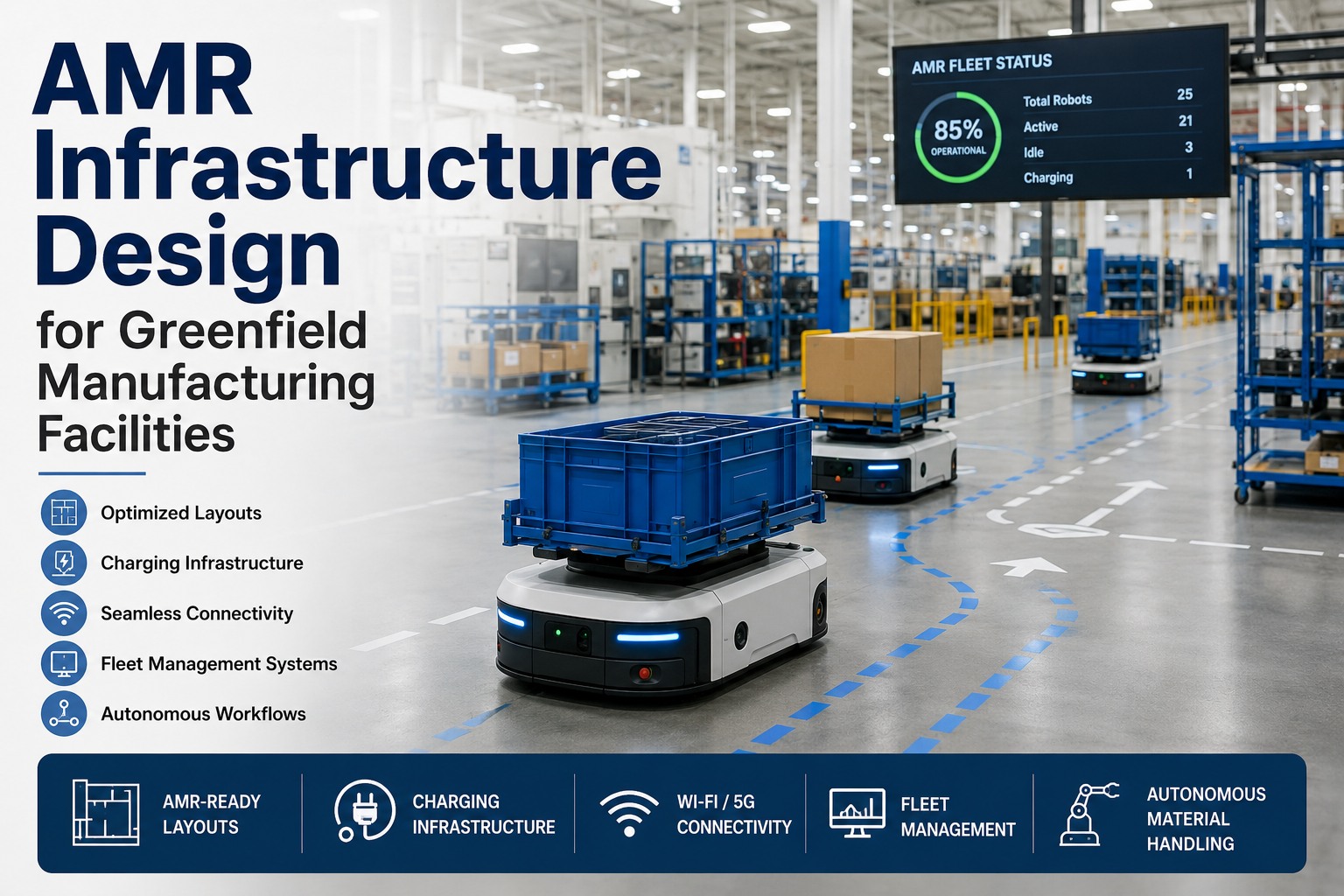
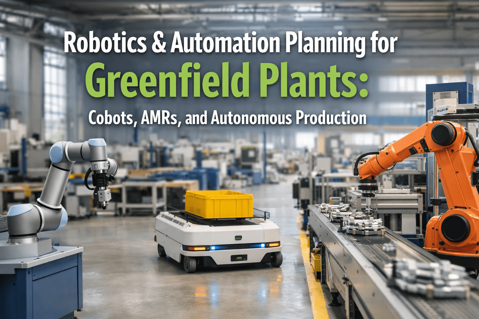
The factories where AMRs actually deliver ROI share one habit: they treat infrastructure as a design problem, not a software problem. The robot is the easy part. The floor flatness, the charging density, the Wi-Fi roaming behavior, the fleet manager's conflict resolution, the MES integration handshake, the safety zones around human work areas — that's where deployments succeed or stall. The global AMR market is racing from $2.75B in 2026 to $7.07B by 2032 (14.4% CAGR), and greenfield facilities have the structural advantage: every infrastructure decision can be built in, not retrofitted. This guide covers the 6 infrastructure pillars, the Wi-Fi 6/7 vs Private 5G decision, charging topology, fleet management architecture, and the implementation mistakes that derail otherwise-good deployments. Book an AMR readiness assessment for your facility.
01
Floor & Layout
Flatness · aisle width · traffic flow
Physical
02
Charging
Opportunity + scheduled · power capacity
Power
03
Wireless Network
Wi-Fi 6E/7 · Private 5G · seamless roaming
Connectivity
04
Fleet Management
Traffic control · VDA 5050 multi-vendor
Orchestration
05
System Integration
MES · WMS · ERP · mission generation
Data
06
Safety & HRI
Demarcated zones · speed limits · LiDAR
Compliance
Why AMRs Need Infrastructure Designed In, Not Bolted On
Retrofit AMR deployments take 2-3x longer and deliver 30-50% lower ROI than greenfield deployments. The reason is simple: every infrastructure decision in a retrofit is a compromise. In a greenfield, every decision is a design choice. Five reasons greenfield AMR design beats retrofit every time.
01
Floor Flatness Designed, Not Ground
AMR navigation accuracy depends on floor flatness within mm-level tolerance. Greenfield pours to spec; retrofits grind and re-pour at $40-80/m². Build it right once.
02
Aisle Geometry Engineered for Traffic
One-way loops, bidirectional widths, intersection geometry, and turn radii all affect throughput. Designed-in flow handles 40-60% more missions per hour than reactive retrofit layouts.
03
Power Capacity Allocated at Single-Line
Charging infrastructure pulls 5-20 kW per station. Greenfield electrical design includes AMR loads. Retrofit projects often hit panel capacity ceilings forcing expensive switchgear upgrades.
04
Network Coverage Engineered, Not Patched
AMRs need continuous overlapping coverage with sub-50ms roaming. Greenfield wireless surveys place APs for AMR traffic patterns. Retrofit projects fight signal dead zones in racking shadows.
05
Safety Zones Drawn Before Walls
Human-robot collaboration zones, marked floors, and physical barriers integrate with the layout — not added as afterthoughts. Greenfield safety design cuts incident risk by 60-80% vs retrofit.
The 6 Infrastructure Pillars · Detailed
Each pillar has its own engineering specification, vendor ecosystem, and failure mode. The deep-dive below shows what to design for each, what to specify in tenders, and how each pillar interacts with the others. Treat them as a system, not a checklist.
Pillar 01
Floor & Layout
Floor flatness FF35-50 minimum on AMR routes. Aisle widths 1.5m one-way, 2.5m+ bidirectional, 3m+ at intersections. Traffic-flow zones planned for one-way loops where possible. No sudden floor transitions; ramps below 3% slope.
Pillar 02
Charging Infrastructure
Hybrid topology: opportunity chargers at workpoints (short top-ups during dwell) + scheduled chargers in dedicated bay. Typical ratio: 1 charger per 5-10 AMRs. Power capacity: 5-20 kW per station. Wireless and contact options for automated docking.
Pillar 03
Wireless Network
Wi-Fi 6E/7 with dedicated SSID for AMRs, overlapping AP coverage, <50ms roaming. Private 5G for ultra-low-latency (URLLC) applications and large facilities. Wi-Fi 7 supports 320MHz channels for high-bandwidth video. QoS prioritization for AMR traffic.
Pillar 04
Fleet Management System
Central traffic controller orchestrates missions, resolves conflicts at intersections, optimizes charging schedules, and integrates with production systems. VDA 5050 standard for multi-vendor coordination — avoid single-vendor lock-in.
Pillar 05
System Integration
MES generates missions from production schedule. WMS triggers warehouse-to-line movements. ERP closes the loop on inventory. Integration via REST API, OPC-UA, or MQTT. Real-time status updates from FMS to enterprise systems.
Pillar 06
Safety & Human-Robot Collaboration
LiDAR safety sensors on every AMR. Demarcated robot zones on floor (paint, tape, lights). Speed-limited zones in human-shared areas (typical 0.5-1.0 m/s). Emergency stops at workstations. ISO 3691-4 compliance for industrial mobile robots.
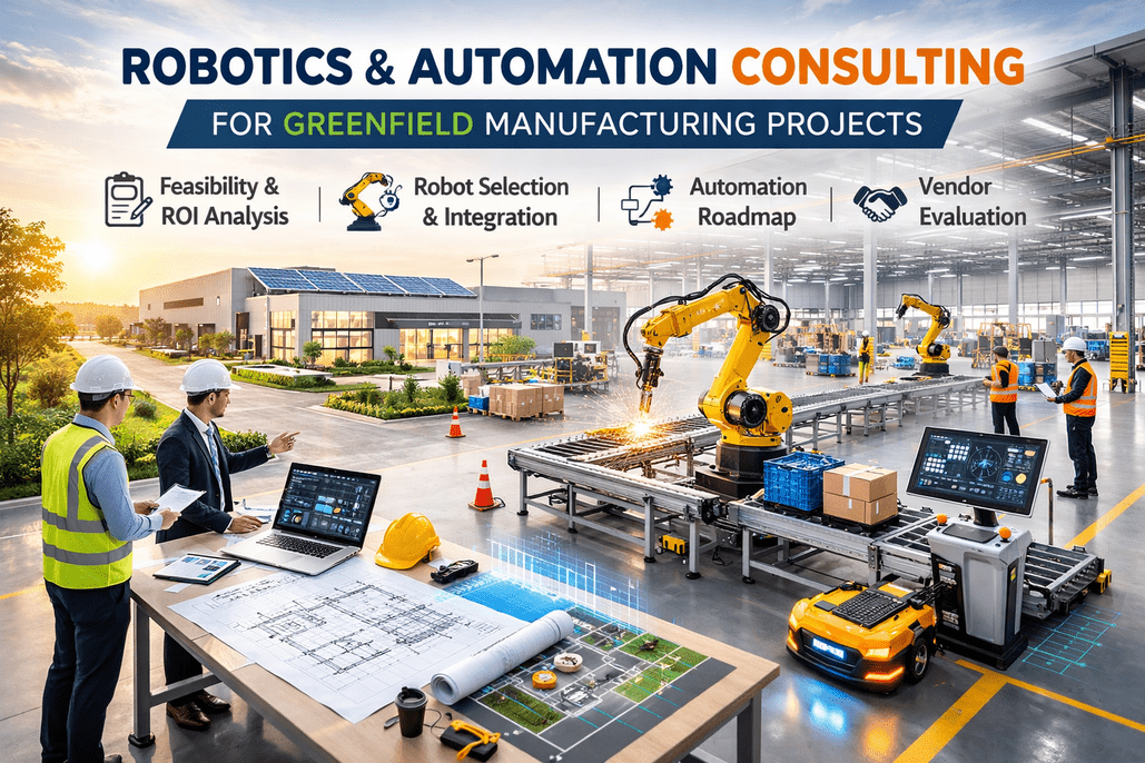
Engineer an AMR-Ready Facility From Day One
iFactory's AMR practice designs greenfield facilities for autonomous logistics — floor flatness specs, aisle geometry, charging topology, wireless coverage, fleet management architecture, MES integration, and ISO 3691-4 safety design. Built-in AMR readiness, not bolted-on retrofits.
Network Architecture · Wi-Fi 6E/7 vs Private 5G
The wireless decision is the single most consequential infrastructure choice for AMR fleets. Wi-Fi 6E/7 dominates most facilities at lower cost. Private 5G wins where ultra-low latency or mission-critical reliability matters. The comparison below maps both options to use cases — most modern facilities run hybrid.
Dimension
Wi-Fi 6E / Wi-Fi 7
Private 5G
Recommended Use
Latency
10-50 ms
<1 ms (URLLC)
5G for safety-critical / high-speed control
Throughput
Up to 9.6 Gbps (Wi-Fi 7, 320 MHz)
1-10 Gbps typical
Either handles AMR video/sensors
Roaming
Seamless AP-to-AP (Wi-Fi 7 multi-link)
Native cellular handover
5G better in large facilities
Cost
$200K-500K (mid-size plant)
$500K-2M+ (CBRS or licensed)
Wi-Fi for most cost-sensitive
Coverage
Dense APs (every 15-30m)
Few base stations cover large area
5G for sprawling layouts
Best Practice
Default for mid-size plants
Where latency <10ms required
Hybrid is increasingly common
Need a wireless architecture review for your AMR fleet? Book a connectivity design session with our network engineering team.
Charging Strategy Template
Charging strategy determines whether your fleet hits 90%+ uptime or constantly cycles to depleted batteries. The four topologies below map to different mission profiles. Most greenfield plants run hybrid — opportunity at workpoints, scheduled for deep charge — with FMS-managed predictive charging.
Topology A
Opportunity Charging
Chargers at workpoints. AMRs top up during natural dwell time (loading, unloading, idle). Keeps fleet always near full charge. Best for high-utilization fleets.
5-10 kW · 30-60s top-ups · high station density
Topology B
Scheduled Charging Bay
Dedicated bay with high-power chargers. AMRs sent for full charge on schedule. Predictable, simple, but requires fleet manager to plan around charge cycles.
15-30 kW · 30-90 min full charge · central bay
Topology C
Battery Swap
Robotic or manual battery swap stations. Zero downtime per swap. Used for heavy-payload AMRs and 24/7 high-utilization operations. Higher CAPEX but maximum fleet utilization.
60-90s swap · battery inventory required
Topology D
Hybrid + Predictive (Recommended)
Opportunity charging at workpoints + scheduled bay for deep charge. FMS predicts battery state, dispatches AMRs to chargers before low alarms. Avoids charging bottlenecks at peak demand.
Mixed kW · FMS-managed · recommended default
Want a custom charging topology design for your fleet? Connect with our AMR design team for a tailored layout.
5 AMR Implementation Mistakes
The same five mistakes appear in nearly every AMR deployment that fails to deliver projected ROI. Each is preventable at the design stage — and almost impossible to fix after construction.
01
Treating AMRs as AGV Replacements
AGVs follow fixed paths; AMRs navigate dynamically. The infrastructure requirements are different. Designing the facility for AGV-style fixed routes throws away the AMR's flexibility advantage.
02
Single-Vendor Lock-In
Proprietary fleet managers can't coordinate AMRs from different vendors. Specify VDA 5050 compatibility from day one. Lock-in costs 20-40% in long-term flexibility and TCO.
03
Under-Specified Floor Flatness
Standard industrial floor (FF20-25) causes AMR navigation errors and cargo drift. AMR routes need FF35-50. Spec it during concrete pour — grinding later costs $40-80/m².
04
Insufficient Charging Density
Charger-to-AMR ratios above 1:15 create queueing at peak production. Plan 1:5-10 with opportunity charging mixed in. Charging bottlenecks crater fleet utilization by 20-30%.
05
Wi-Fi Coverage Gaps in Racking Shadows
Standard office Wi-Fi placement leaves dead zones behind racking, in narrow aisles, and at intersections. Conduct AMR-specific RF surveys; place APs for robot height (~1m), not human height (~2m).
Avoid these mistakes with a designed-in AMR readiness review. Book an infrastructure assessment with our automation team.
Expert Perspective
Every failed AMR deployment I've audited fails for the same reason: the team bought robots when they should have bought infrastructure. The robot vendor demos beautifully — three AMRs in a clean test cell, perfect Wi-Fi, instant charge. Then 60 robots hit the production floor, the Wi-Fi can't handle the roaming load, the chargers queue up at lunch break, and the fleet manager can't coordinate across two vendors. The deployments that work get this right: they specify floor flatness in the concrete contract, they put APs at robot height during RF surveys, they pick a fleet manager that speaks VDA 5050, and they integrate the FMS with MES before robot one arrives. Get the six pillars right and the robots run themselves. Get them wrong and even the best robot can't save the deployment.
— AMR Deployment Best Practice
FF35-50
Floor flatness spec for AMR routes
VDA 5050
Multi-vendor AMR coordination standard
1:5-10
Optimal charger-to-AMR ratio
ISO 3691-4
Industrial mobile robot safety standard
Bottom Line · Buy Infrastructure, Then Robots
AMR deployments succeed when infrastructure is the first decision and robots are the last. Floor flatness designed into the concrete contract. Aisle geometry engineered for traffic flow. Power capacity allocated for charging at single-line. Wireless coverage planned for robot height and overlapping AP roaming. Fleet management chosen for VDA 5050 multi-vendor compatibility. MES integration scoped before robot one arrives. Safety zones drawn before walls. Get the 6-pillar infrastructure stack right and the AMRs deliver 40-60% more missions per hour, 30-50% better ROI, and the operational flexibility that justified the technology in the first place. The robot is the easy part. The infrastructure is what makes the deployment work.
Design Your Next Facility for AMRs From Day One
iFactory's AMR practice engineers the full 6-pillar infrastructure stack — AMR-grade floor, traffic-flow aisles, charging topology, wireless coverage, VDA 5050 fleet management, MES integration, and ISO 3691-4 safety design. Greenfield AMR readiness built in, not bolted on.
Frequently Asked Questions
What are the 6 infrastructure pillars for AMR deployment?
1) Floor & Layout (FF35-50 flatness, 1.5-3m aisles), 2) Charging (opportunity + scheduled, 1:5-10 ratio), 3) Wireless Network (Wi-Fi 6E/7 or Private 5G, <50ms latency), 4) Fleet Management (VDA 5050 multi-vendor), 5) System Integration (MES/WMS/ERP via REST/OPC-UA/MQTT), 6) Safety & HRI (ISO 3691-4, zoned speeds, LiDAR). Miss any one and the deployment stalls in pilot purgatory.
Wi-Fi 6E/7 or Private 5G for AMRs?
Wi-Fi 6E/7 handles most mid-size plants at $200K-500K. Latency 10-50ms, throughput up to 9.6 Gbps (Wi-Fi 7, 320 MHz channels), seamless AP roaming. Private 5G wins where <1ms URLLC latency matters or facility is sprawling — but costs $500K-2M+. Most modern facilities run hybrid: Wi-Fi for general fleet, 5G for safety-critical or high-speed control.
What charging strategy works best for AMR fleets?
Hybrid is the new standard: opportunity charging at workpoints (5-10 kW, 30-60s top-ups during natural dwell) + scheduled bay (15-30 kW, 30-90 min full charge). FMS predicts battery state and dispatches before low alarms. Charger-to-AMR ratio: 1:5-10. Battery swap is option for heavy-payload 24/7 fleets. Avoid wait-til-low charging — it bottlenecks at peak production.
What is VDA 5050 and why does it matter?
VDA 5050 is the German automotive industry standard for AMR-to-fleet-manager communication. It enables multi-vendor AMR coordination — robots from different brands managed by one fleet manager. Without VDA 5050 you're locked into a single vendor's robots and their fleet manager's licensing. Specify VDA 5050 compatibility in every tender. Single-vendor lock-in costs 20-40% in long-term TCO.
What floor flatness do AMRs need?
FF35-50 on AMR routes — significantly tighter than standard industrial floor (FF20-25). Lower flatness causes navigation errors, cargo drift, and AMR vibration that damages sensors. Greenfield pours to spec during construction. Retrofit grinding costs
$40-80/m² and disrupts operations. Spec floor flatness in the concrete contract before pour.
Book a floor specification review with our AMR design team.