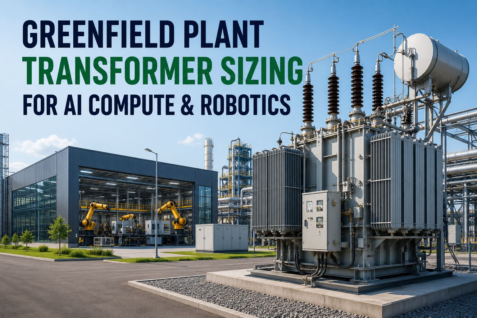
Greenfield plant transformer sizing has changed permanently. A traditional manufacturing facility planned for 5–15 kW per rack of conventional automation. An AI-native plant in 2026 adds 40–60 kW per GPU rack, 3–7 kW per collaborative robot charging station, and harmonic injection from VFD populations that degrades standard transformer insulation unless the K-factor is specified correctly. The engineers who size for the 2020 plant — using 1.2× load headroom and standard K-1 distribution transformers — create a retrofit problem that costs four to six times the greenfield specification to fix after commissioning.
Get your transformer sizing validated for AI compute and robotics loads — iFactory specifies kVA, K-factor, harmonic mitigation, and load schedule before your electrical contractor prices the MV switchgear.
2026 Greenfield Load Profile
What's Actually Drawing Power in an AI-Native Manufacturing Plant
Traditional sizing ignores the AI compute, robotics, and harmonic loads that now dominate the greenfield load schedule. Each category requires a different transformer specification strategy.
Process & HVAC Loads
VFD Drive Loads
Robotics & AMR Loads
AI & Edge Compute Loads
The kVA Sizing Calculation: Step-by-Step for Mixed AI + Robotics Loads
Transformer kVA sizing for an AI-native greenfield plant must account for three factors that standard facility calculations omit: the continuous 24/7 nature of AI server loads (no diversity factor), the duty cycle of robotic and VFD loads (typically 65–85% simultaneous demand), and the harmonic derating penalty that reduces usable transformer capacity below nameplate kVA when supplying non-linear loads without K-factor specification.
Sum Connected Load by Category
Compile every load from the electrical equipment list, grouped by category: process/HVAC motors, VFD-driven equipment, robotics, and AI/edge compute. Express each load in kW and record the power factor (typically 0.85–0.95 for industrial loads).
kVA per load = kW ÷ Power Factor (PF)
Apply Demand Factors by Load Type
Not all loads run simultaneously at full capacity. Apply demand factors per load category: AI compute loads = 1.0 (continuous 24/7, no diversity); VFD motor loads = 0.65–0.75 (staggered starts, variable duty); robotic cells = 0.70–0.85 (cycle-dependent); HVAC/process = 0.80–0.90 depending on facility type.
Demand kVA = Connected kVA × Demand Factor
Apply Harmonic Derating for Non-Linear Loads
Standard transformers serving significant VFD, robotics, or AI compute loads overheat at nameplate kVA due to additional eddy-current losses from harmonic currents. Without a K-factor rated transformer, derate the transformer capacity to 85–90% of nameplate. With a properly rated K-factor transformer (K-13 for VFD, K-20 for GPU loads), operate at full nameplate — no derating required.
Effective kVA = Nameplate kVA × 0.85 (for >30% non-linear load)
Add Growth Headroom and Select Standard Size
AI-native plants expand compute faster than any other load category. Best practice: size the main transformer at 2× day-one demand load, not the traditional 1.2×. After applying demand factors and harmonic derating, add 100% capacity headroom and select the nearest standard transformer size above the calculated requirement.
150 / 225 / 300 / 500 / 750 / 1,000 / 1,500 / 2,000 / 2,500 kVA
Need the sizing calculation run for your specific load schedule? Book a transformer sizing session with iFactory — we calculate kVA demand, apply category-specific demand factors, and specify K-factor requirements from your equipment list before your electrical contractor quotes switchgear.
K-Factor Selection: The Specification That Protects Transformer Life
K-factor is the IEEE C57.110 standard for rating transformers against harmonic heating from non-linear loads. A transformer rated K-13 can supply harmonic current spectra that produce 13× the eddy-current heating of a linear load without exceeding its design temperature rise. Standard transformers without K-rating overheat silently — reducing insulation life from the designed 20+ years to as few as 5–7 years in VFD-heavy environments — without triggering any immediate alarm.
K = Σ (h² × Ih²)
where h = harmonic order, Ih = per-unit current at harmonic h
In practice: specify K-13 as the minimum for any greenfield plant with VFD motor loads. Upgrade to K-20 when GPU clusters or UPS-backed compute exceeds 20% of transformer load. Never apply a K-1 standard transformer to a VFD-heavy or robotics-dense production environment without derating the nameplate to 85%.
Need K-factor specified for each transformer on your one-line diagram? Talk to iFactory's electrical engineering team — we calculate the harmonic load profile per transformer and write K-factor into your procurement specification before RFQ.
Transformer Sizing for the AI Plant You're Building — Not the 2020 Factory That Spec Was Written For
iFactory's electrical infrastructure team sizes your greenfield transformers for real 2026 loads — AI compute, robotics charging, VFD motor populations, and the harmonic spectrum they inject. We specify kVA, K-factor, harmonic mitigation, and 2× growth headroom before your MEP engineer prices the one-line diagram.
Harmonic Mitigation: What IEEE 519 Requires and How to Design It In
IEEE 519 sets the voltage harmonic limit at the point of common coupling (PCC): total harmonic distortion (THD) must remain below 5% for most industrial systems. A greenfield plant with large VFD populations and GPU compute loads will exceed this limit without designed-in harmonic mitigation — causing spurious breaker trips, degraded AI vision system performance, and accelerated transformer insulation aging.
Passive Harmonic Filters
LC filter networks tuned to the dominant harmonic frequencies (5th, 7th, 11th, 13th) installed on MV bus sections serving large VFD populations. Low-cost, no active components, but fixed to specific harmonics — not adaptive to changing load profiles.
Best for: Stable, predictable VFD loads
Active Harmonic Filters (AHF)
Power electronics that inject cancellation currents to neutralize all harmonic orders simultaneously. Adapts in real time to changing load profiles — ideal for plants where AI compute loads vary with workload and robot production schedules shift by shift.
Best for: Variable AI + robotics loads
12-Pulse / 18-Pulse Drive Topology
Multi-pulse VFD input rectifiers that cancel the dominant 5th and 7th harmonics through phase shifting — reducing THD-I from 80% (6-pulse) to 8–15% (12-pulse). Specified at the drive procurement stage, not as a retrofit filter. The most cost-effective harmonic mitigation for large drive loads above 100 kW.
Best for: Large VFD drives ≥100 kW
Line Reactors at Drive Input
3–5% impedance line reactors installed at the input to each 6-pulse VFD reduce THD-I from 80%+ to 30–40% at minimal cost. Reduces the K-factor requirement from K-20 to K-13 for most VFD loads. First line of defense in every AI plant electrical design — specified at drive level, not as a system filter.
Best for: Cost-effective per-drive mitigation
Want harmonic mitigation designed into your plant electrical layout? Book a harmonic mitigation design session with iFactory — we specify passive/active filters, 12-pulse drive topology, and line reactors at the plant layout stage before any switchgear is procured.
Expert Perspective
The substations we audit at year 3 of AI-native plant operation almost always have the same problem — they were sized for the 2020 plant, not the 2026 plant. Edge compute density, robot charging, AI vision lighting, and continuous digital twin operations consume 2–3× the electrical capacity that traditional manufacturing planning assumed. Harmonic injection from larger VFD populations corrupts AI vision systems. Designing the transformer specification for the 2026 plant — K-rated, harmonic mitigation from day one, 2× capacity headroom — costs 5–10% more at FEED and prevents the retrofit that costs 4–6× per upgrade later.
electrical capacity of AI-native plants vs. traditional manufacturing — the load headroom most FEED specs miss
cost multiplier to retrofit transformer capacity post-commissioning vs. specifying correctly at FEED stage
lead time for large power transformers in 2026 — order before design freeze or accept the delay risk
Specify Your Transformers for the Plant You're Building — Before Design Freeze
iFactory's greenfield electrical team calculates kVA demand by load category, applies harmonic derating, specifies K-factor per transformer, designs the harmonic mitigation strategy, and specifies 2× growth headroom — before your MEP contractor prices the one-line diagram. Transformer lead times are 18–36 months. Order on the right spec the first time.
Frequently Asked Questions
How much transformer kVA does a greenfield AI plant require?
An AI-native plant consumes 2–3× the electrical capacity of a traditional facility. A 50,000 sq ft plant with 4 GPU racks (160 kW AI), 20 cobots (80 kW), and 500 kW VFD motor loads has a calculated demand of approximately 800 kVA before headroom. Best practice is to size the main transformer at 2× demand — 1,500–2,000 kVA — to absorb AI compute expansion without a retrofit.
What K-factor transformer does a plant with VFD drives and GPU racks require?
Specify K-13 minimum for any transformer serving significant VFD load (6-pulse drives at 30–80% THD-I). Upgrade to K-20 when GPU compute racks exceed 20% of the transformer's total load — GPU switch-mode power supplies and UPS rectifiers drive THD-I to 60–100% on dedicated circuits. A standard K-1 transformer serving these loads thermally degrades to 85% nameplate capacity and loses years of insulation life silently.
Why does AI compute load require different transformer sizing than conventional plant loads?
GPU server loads are continuous (demand factor 1.0 — no diversity), highly non-linear (switch-mode power supplies inject significant harmonics), and have rapid transient load swings of 30–50% in milliseconds as batches complete. Standard industrial transformer sizing applies 0.65–0.80 demand factors to motor loads; AI racks get none. Combined with the harmonic penalty, a GPU-dense deployment requires a transformer 40–60% larger than a conventional load calculation would suggest.
What is the IEEE 519 harmonic limit and how does a greenfield plant meet it?
IEEE 519 requires voltage THD below 5% at the point of common coupling (PCC) for most industrial facilities. A plant with large 6-pulse VFD populations and GPU compute will exceed this without designed-in mitigation. The most cost-effective design sequence: specify 12-pulse or 18-pulse drives for large motors (reduces THD-I at source); install 3–5% line reactors at remaining 6-pulse drives; add active harmonic filters on MV bus sections serving AI compute loads. K-rated transformers handle thermal heating but do not reduce network THD — both specifications are necessary.
How long are transformer lead times in 2026 and how should greenfield planning account for them?
Large power transformer lead times in 2026 range from 18 months for standard LV distribution units to 36+ months for MV substation transformers, reflecting supply chain constraints from the global AI data center buildout. For greenfield plant projects, transformer procurement must be initiated at FEED completion — before detailed engineering is finished — using a preliminary load schedule. Ordering on a correctly specified K-factor and kVA rating at FEED is far less risky than ordering on a generic specification and issuing an amendment at detailed design that extends lead time further.