A single lightning strike delivers 200,000 amperes in a 10/350 microsecond wave — enough to ignite combustibles, fry every PLC on the floor, and crash SCADA. Lightning-related fires account for 3 to 5% of all US commercial property insurance claims, with annual payouts exceeding $2 billion to SMBs. Manufacturing plants designed without IEC 62305 or NFPA 780-compliant protection face uninsurable risk in 2026. A properly engineered system — air terminals, down conductors, sub-10Ω grounding, layered SPDs at every LPZ boundary, and full equipotential bonding — protects $50M+ in equipment for less than 1% of plant CapEx. Book a plant electrical consultation to design your facility's protection.
The 4 Lightning Protection Levels — Stringency by Facility Risk
IEC 62305 assigns one of four Lightning Protection Levels based on a documented risk assessment. The higher the level, the more stringent the system — denser air terminals, tighter mesh, higher-rated SPDs. The pyramid below shows how facility type maps to LPL.
Highest Protection
High Protection
Standard Protection
Basic Protection
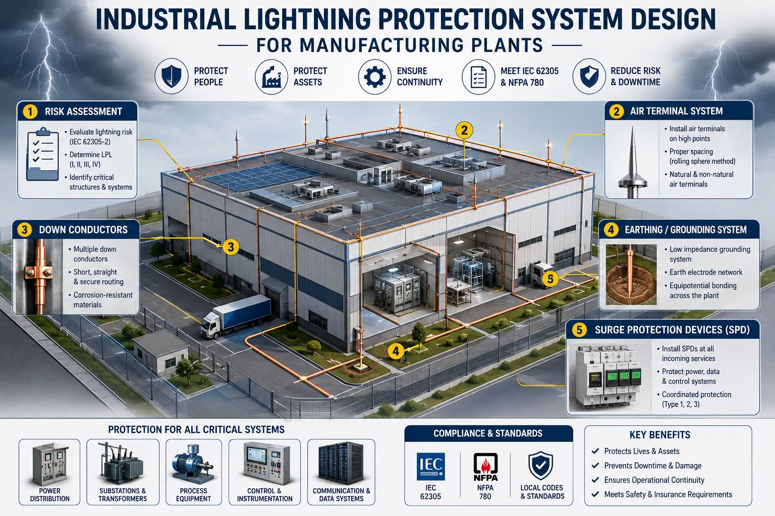
The 6 Components — Anatomy of an IEC 62305 / NFPA 780 System
A compliant lightning protection system is a layered architecture of six interlocking components. Each performs a distinct role in the strike-to-ground current path. Skip one and the others cannot compensate.
Air Terminals
Lightning rods at highest roof points intercept the downward leader before it can strike the structure itself.
Down Conductors
Carry strike current from roof to ground. Min 2 per structure · 10m spacing for LPL I, 20m for LPL IV.
Earth Termination
Ground electrodes safely dissipate strike energy into soil. Mesh + ring + rods for sensitive industrial sites.
Equipotential Bonding
All structural steel, pipes, cable trays bonded at single point. Eliminates dangerous flashover voltages during strikes.
Surge Protective Devices
Layered SPDs at every LPZ boundary divert surge currents. Type 1 (service), Type 2 (distribution), Type 3 (point of use).
Separation Distances
Minimum clearances prevent side-flash between LPS conductors and other metallic systems. Critical for ATEX zones and structures over 60m.
Need this 6-component architecture sized to your specific facility? Book a plant electrical consultation — we will produce the LPS design package per IEC 62305 / NFPA 780.
The 3 Air Terminal Design Methods — Visualized
Air terminal placement uses one of three calculation methods. The visualizations below show how each method covers the same building differently. Choose by structure complexity — not by familiarity.
Rolling Sphere Method
A virtual sphere (R = 20m for LPL I, 60m for LPL IV) rolls over the structure. Any surface it touches needs an air terminal. Most accurate for complex geometries.
Mesh / Grid Method
Conductor mesh creates a Faraday cage over the roof. Mesh tightens with higher LPL (5×5m for LPL I, 20×20m for LPL IV). Effective on large flat geometries.
Protective Angle Method
A cone of protection beneath an air terminal. Angle α determined by LPL and terminal height. Simple to apply on small, uncomplicated structures.
NFPA 780 vs IEC 62305 — Two Frameworks, One Engineering Decision
Two standards govern industrial lightning protection globally. They share scientific foundations but apply fundamentally different design philosophies. Choose the right one — or both — for your facility.
NFPA 780:2023
- By structure type and use
- Type 1 · 2 · 3 SPDs (UL 96A / UL 1449)
- Used: USA · most domestic projects
- Best: Single-region US facility
- Moderate · checklist documentation
IEC 62305:2024
- Risk calculation → LPL I–IV
- Class I · II · III SPDs (IEC 61643)
- Used: EU · UK · Asia · most international
- Best: Complex risk profiles · global sites
- Extensive · calculation-heavy
Need both frameworks covered for a multi-region greenfield? Talk to our plant electrical team — we will produce the dual-standard compliance package for your facility.
Expert Perspective: The 3 Failures Behind Every Lightning Incident We've Audited
Across hundreds of industrial site audits, three failure modes account for almost every documented post-installation strike incident. First, separate grounding systems left unbonded. Industrial facilities historically maintain dedicated grounds for lightning, electrical equipment, instrumentation, and telecommunications — when these grids carry different potentials during a strike, the voltage difference can exceed air gap breakdown and create flashover that ignites combustibles and damages PLCs. Both IEC 62305-3 and NFPA 780 now require single-point bond integration. Second, surge protective devices specified by Class label rather than current rating. The Class name doesn't dictate the required Iimp — the facility's LPL does. SPDs sized by Class without LPL verification routinely fail under actual strike conditions. Third, dissipation arrays and ESE devices marketed as strike-prevention. Despite vendor claims, peer-reviewed evidence does not support their preventive efficacy — they are not accepted by regulators or insurers as standalone substitutes for compliant LPS. The plants that survive lightning seasons treat bonding as the core of their protection strategy, not an afterthought.
— iFactory Greenfield Consulting, Plant Electrical Practice 2025 to 2026